Support block system

a technology of support blocks and blocks, applied in the direction of machine supports, other domestic objects, mechanical apparatus, etc., can solve the problems of increased damage to the interior of the building, weight of the blocks, difficult and bulky for users to move and install, etc., to prevent damage to the underlying roof surface, facilitate the use of the device, and the effect of sufficient strength

Active Publication Date: 2008-10-28
FREEDOM
View PDF30 Cites 58 Cited by
  • Summary
  • Abstract
  • Description
  • Claims
  • Application Information

AI Technical Summary

Benefits of technology

[0015]These blocks are preferably made of a high-density UV resistant plastic material, such as ABS, polycarbonate, fiberglass mix or any other suitable material that achieves the necessary functions of the device. These devices prevent damage to the underlying roof surface, while at the same time having sufficient strength so as to support loads of up to 100 lbs. These blocks are also relatively lightweight, which allows a party utilizing the blocks to carry a stack of nested blocks together upon a roof for placement. While upon the roof, the blocks can be removed from their nested position and assembled and placed in a desired position and orientation. The support blocks of the present invention are so configured so that in the event that a block at a raised height is required, such an elevated block arrangement can be obtained by removing a first block from a nested position upon a second block and rotating the first block 90°, and then replacing the first block over the second block. Such a configuration allows for a rise of a predetermined vertical height adjustment and facilitates the ease and use of the device upon a roof or other designated surface.
[0016]In use, once the blocks are in place, a support rail is placed within the channel in the top portion of the support block, and various attachments may be inserted into the track portion of the portion rail. The conduit is then connected to or brought into contact with the various attachment devices and connected. Such a system provides a significant improvement over the prior art in that it eliminates the major disadvantages of the prior art system and devices that have been previously described and discussed.

Problems solved by technology

If damage to the surface were to occur, for example in the instance of a roof, damage to the underlying roof could cause additional damage to the interior of the building.
Another problem that occurs in the prior art is that the weight of the blocks that are placed upon the roof in order to ensure the stability of these conduits are many times burdensomely heavy and thus difficult and bulky for a user to move and install.
Another feature that exists in the prior art is that some of the devices utilized in the prior art have inherent limitations because of their size and configurations and do not allow for the placement of multiple pipes or conduit to be run over a designated distance.
However, each of these systems has had inherent problems associated with them.
This system has many limitations.
One problem is that significant damage can be caused to the roofing material by wooden planks.
This damage is incurred not only from the weight of materials but also by movement of the planks along the surface of the roof as the conduit connected thereto expands and contracts in response to various thermal conditions.
Furthermore, in climates where the devices are exposed to water in various forms, the increased exposure to moisture causes the wood to rot and the unprotected metal to rust and therefore requires frequent replacement and repair.
Another problem that exists in such an embodiment is that the wooden planks must be shimmed or cut in order to accommodate various height and slope requirements depending upon the conduit that is being mounted.

Method used


Image

  • Support block system
  • Support block system
  • Support block system

Examples


Embodiment Construction

[0030]While the invention is susceptible of various modifications and alternative constructions, certain illustrated embodiments thereof have been shown in the drawings and will be described below in detail. It should be understood, however, that there is no intention to limit the invention to the specific form disclosed, but, on the contrary, the invention is to cover all modifications, alternative constructions, and equivalents falling within the spirit and scope of the invention as defined in the claims.

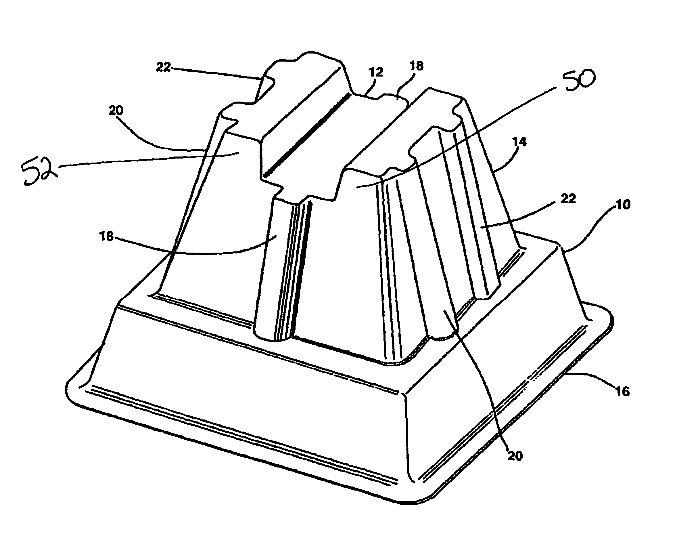
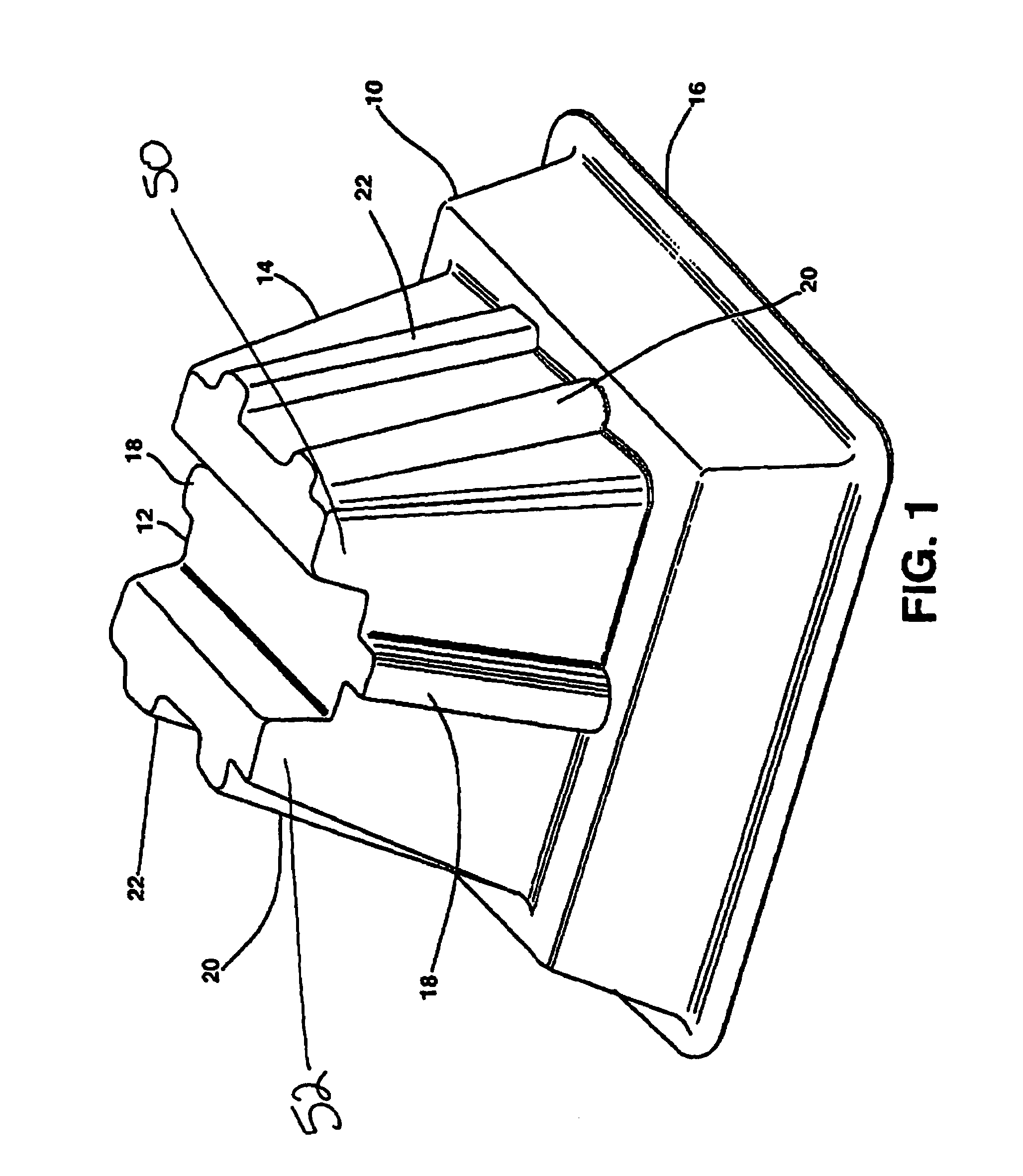
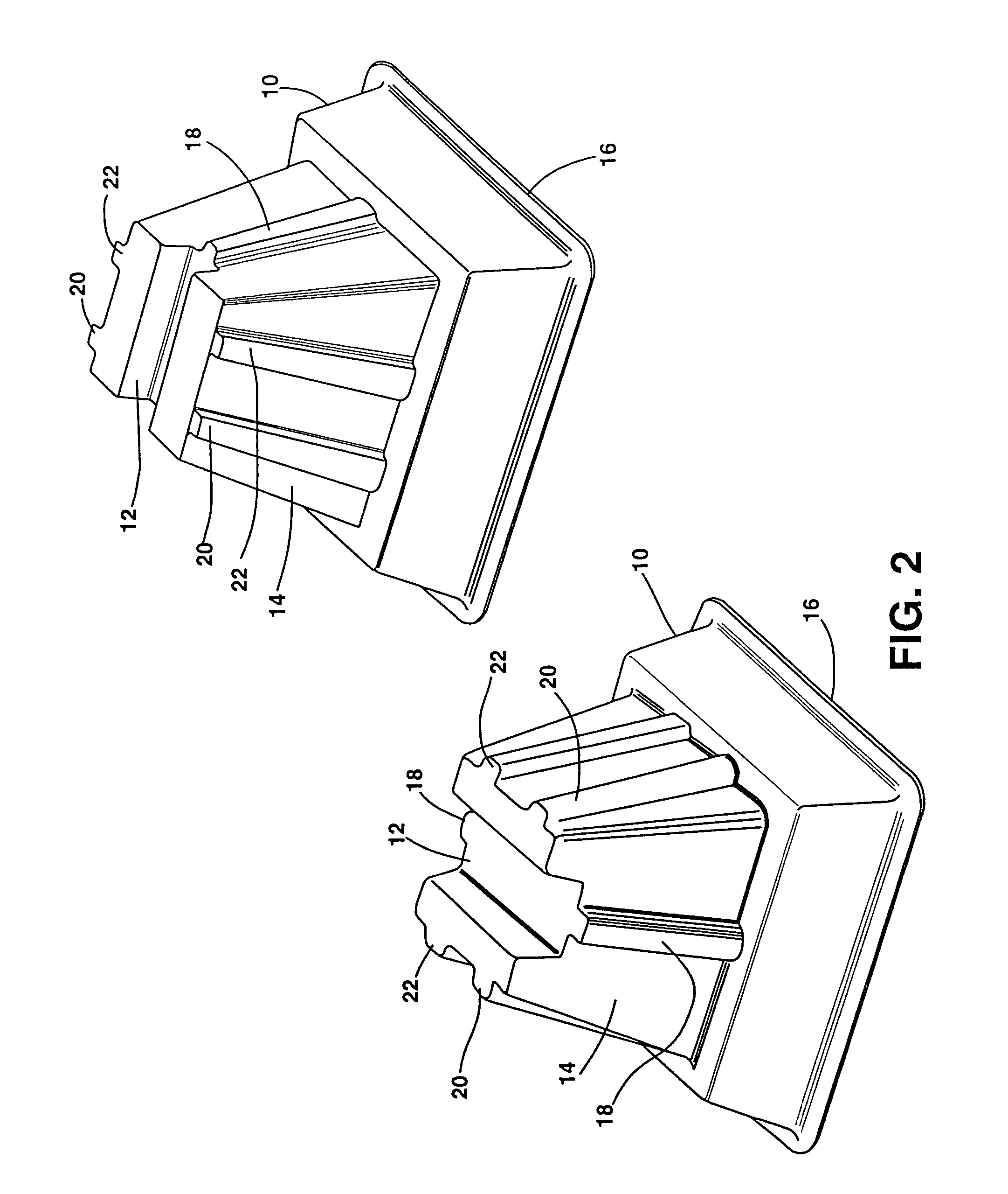
[0031]The present invention is a system for mounting pipes upon a building roof or structure. FIGS. 1-10 of the present invention show this preferred embodiment of the invention both together as well as in its individual pieces as they are described in the present invention. Referring first to FIG. 1, the support block 10 used in the present invention is shown. The support block 10 has a body (which is also 10), which includes an upper portion 14, a channel 12 and a base 16. The b...


PUM


Abstract

A system and device for installing and mounting conduit upon a surface such as a roof. The system made up of at least one support block having a base and an upper portion, a support rail and a variety of attachments for holding conduit to the rail. Each of the various blocks in the system configured to nest when oriented in a first direction to stack in an elevated position having a greater height when oriented in a second direction. These pieces are configured to work together to provide a mounting system with significant advantages over other devices that exist in the prior art.

Description

BACKGROUND OF THE INVENTION[0001]1. Field of the Invention[0002]The present invention generally relates to devices used in the installation and mounting of elongated tubular material such as pipes, conduit and wire over and across a surface, and more particularly to installation and mounting of such items upon a generally horizontally disposed surface such as a roof or floor.[0003]2. Background Information[0004]Many features of modern construction provide convenience by allowing a party to simply and easily access items from a distant location. Examples of such devices include plumbing, heating, ventilating and air conditioning systems. In many of these instances needed materials such as natural gas, electricity, water, and other items are transported from one location to another through a conduit. These conduits must be permanently attached in one location so as to support the conduit while preventing the conduit from being damaged or moved out of a desired alignment and position.[...

Claims


Application Information

Patent Timeline
Patent Type & Authority Patents(United States)
IPC IPC(8): F16L3/08E04C5/16
CPCF16L3/02
Inventor SMART, KENNETH L.TIDWELL, TERRY K.
Owner FREEDOM
Why Eureka
Try Eureka