Vacuum gate

a vacuum gate and gate valve technology, applied in the direction of valve details, valve housings, valve arrangements, etc., can solve the problem of self-locking of the gate door, and achieve the effect of easy opening & closing of the chamber

Inactive Publication Date: 2008-10-28
LEADING PRECISION
View PDF7 Cites 10 Cited by
  • Summary
  • Abstract
  • Description
  • Claims
  • Application Information

AI Technical Summary

Benefits of technology

[0014]It is an object of the present invention to provide an improved vacuum gate that can airtight the vacuum chambers and can open & close the chambers easily even when the thrust pressure on the doors are enormous different pressure between the chambers and outside environment.
[0015]It is another object of the present invention to provide an improved vacuum gate that is purely based on mechanical principle and mechanical mechanism that can sustain enormous pressure difference (both in positive and negative pressure differences) and can also provide large force to open and close valve easily.
[0016]It is another object of the present invention to provide an improved vacuum gate that can overcome the shortcoming and the default of the conventional vacuum gates, which have insufficient transversal forces to maintain the airtight condition between the vacuum chambers, or between valve and the valve contact surface of the vacuum chamber.
[0017]The improved vacuum gate of the present invention utilizes the reverse L-shaped of the first guiding trench to guide and allow the gate door to move both in vertical and horizontal directions in such that the vacuum gate can airtight the vacuum chambers and provide enough force to open and close the vacuum chambers even when the vacuum pressure is increased or when the difference in thrust pressure is increased between the two vacuum chambers. The design in the vacuum gate of the present invention can prevent the O-ring used in the vacuum gate being worn out or damaged. The design of the present invention can also overcome the shortcoming of the prior art that has to adopt a special valve and a special O-ring for limited application. The specific design of the vacuum gate of the present invention can be enlarged and integrated with different gate boxes to accommodate the large chambers. Further, when the pneumatic cylinder lost power, the gate door would be in a self-locked position.
[0023]The vacuum gate of the present invention can be used to accommodate a large size of chamber based on the same operating principles and design. The number of the pneumatic cylinder used is increased, and the pneumatic cylinders and flexible sealed tubes are connected in parallel in the large size of vacuum gate.
[0024]One of objects of the present invention is to provide an improved vacuum gate that different types of flexible sealed tubes or bellows can all be used in between the bottom part of the gate box and the transmission rods for the vacuum effect. The usage of the flexible seal tubes and the bellow is depended on the application of the vacuum gate, when vacuum gate utilized in the condition of the gate valve close-open cycles is less than 100,000 times per year, flexible sealed tubes are recommended as it is cheaper to maintain, whereas, when the application of the vacuum gate in the condition of the close-open cycles is more than 100,000 times per year, bellows are recommended as good quality of bellows has longer life span and there is no need for repairing the O-rings.

Problems solved by technology

Further, when the pneumatic cylinder lost power, the gate door would be in a self-locked position.

Method used


Image

  • Vacuum gate
  • Vacuum gate
  • Vacuum gate

Examples


Embodiment Construction

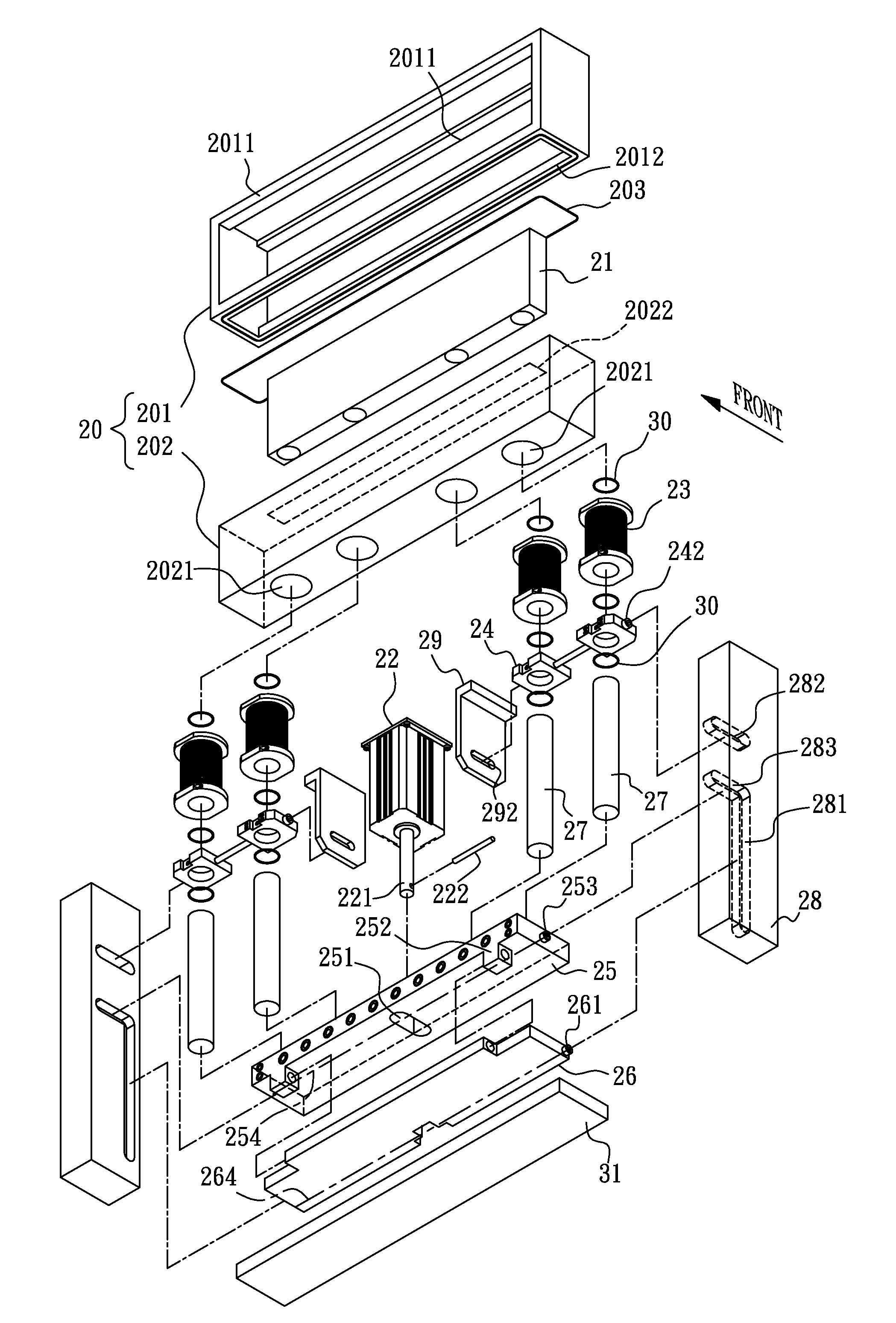
[0044]Refer to FIGS. 4-6, assembly views of an improved vacuum gate capable of airtight isolating or interconnecting two vacuum chambers. FIG. 4 illustrates the improved vacuum gate in a first state in accordance with a first preferred embodiment of the present invention. The vacuum gate of the present invention comprises a gate box 20, a gate door 21, a plurality of flexible sealed tubes 23, at least one swinging device 24, at least one pneumatic cylinder 22, a pair of first supporting units 28, a movable board 25, a thrust board 26 and a plurality of transmission roads 27. The gate box 20 further comprises a top body 201 and a bottom body 202, wherein valve hole 2011 is provided at the front and rear portions respectively of the top body 201 shown in FIG. 4, and a connecting top opening 2012 is provided at the bottom portion of the top body 201. A connecting bottom opening 2022 is provided at the top portion of the bottom body 202, and a plurality of first holes 2021 is provided a...


PUM


Abstract

The improved vacuum gate of the present invention is capable of airtight isolation or interconnecting between two vacuum chambers. The improved vacuum gate is based on mechanical mechanism which simplifies the whole vacuum gate structure and provides more practical and economical usage. Two reverse L-shaped of the first guiding trenches are used to guide and allow the gate door of the gate box to move both in vertical and horizontal directions in such that the vacuum gate can air seal the vacuum chambers and provide enough force to open and close the vacuum chambers even when the vacuum pressure is increased or when the difference in thrust pressure is increased between the two vacuum chambers. Further, different types of the tubes and bellows can be used in the improved vacuum gate depended on the application of the vacuum gate in the different conditions of the gate valve close-open cycles.

Description

CROSS-REFERENCE TO RELATED APPLICATIONS[0001]This application is a Continuation in part of U.S. patent application Ser. No. 11 / 183,206, filed on Jul. 18, 2005, now pending, which is hereby incorporated by reference in its entirety.[0002]Although incorporated by reference in its entirety, no arguments or disclaimers made in the parent application apply to this divisional application. Any disclaimer that may have occurred during the prosecution of the above-referenced application(s) is hereby expressly rescinded. Consequently, the Patent Office is asked to review the new set of claims in view of all of the prior art of record and any search that the Office deems appropriate.[0003]1. Field of Invention[0004]The present invention relates to a vacuum gate valve, and more particularly to an improved vacuum gate capable of airtight isolating or interconnecting two vacuum chambers.[0005]2. Description of the Related Art[0006]A vacuum gate plays an important role in many types of equipment t...

Claims


Application Information

Patent Timeline
Patent Type & Authority Patents(United States)
IPC IPC(8): F16K3/00
CPCF16K3/0254F16K27/044F16K51/02F16K3/18
Inventor CHEN, HWA-FU
Owner LEADING PRECISION
Why Eureka
Try Eureka