Multiphased and multidimentional wave converter

a multi-phase and multi-dimentional wave technology, applied in the direction of electrical equipment, control systems, sea energy generation, etc., can solve the problems of short operating life, excessively high electricity price, and no of the technical solutions disclosed in the disclosures, so as to improve the strength of the structure, and reduce the cost of operation

Inactive Publication Date: 2008-10-28
OTTERSEN HANS OLAV
View PDF12 Cites 28 Cited by
  • Summary
  • Abstract
  • Description
  • Claims
  • Application Information

AI Technical Summary

Benefits of technology

[0005]In the new invention disclosed herein, any desired number of different phases may be employed, thereby exploiting the energy derived from the relative motions between each single buoyant element 1 and the two closest buoyant elements. This produces more energy and also provides a simpler design. In this invention, it is possible to omit said construction of the aforementioned patent application, the construct

Problems solved by technology

There are many other patents in this field, but none of the technical solutions disclosed therein produce a lot of energy in a simple and inexpensive manner.
Due to the motion of the wave converter not corresponding to the motion of the water, this solution does not produce a lot of energy.
The solution of Cockerell provides a short operating life and an excessively high electricity price.
This solution has proven

Method used


Image

  • Multiphased and multidimentional wave converter
  • Multiphased and multidimentional wave converter
  • Multiphased and multidimentional wave converter

Examples


Embodiment Construction

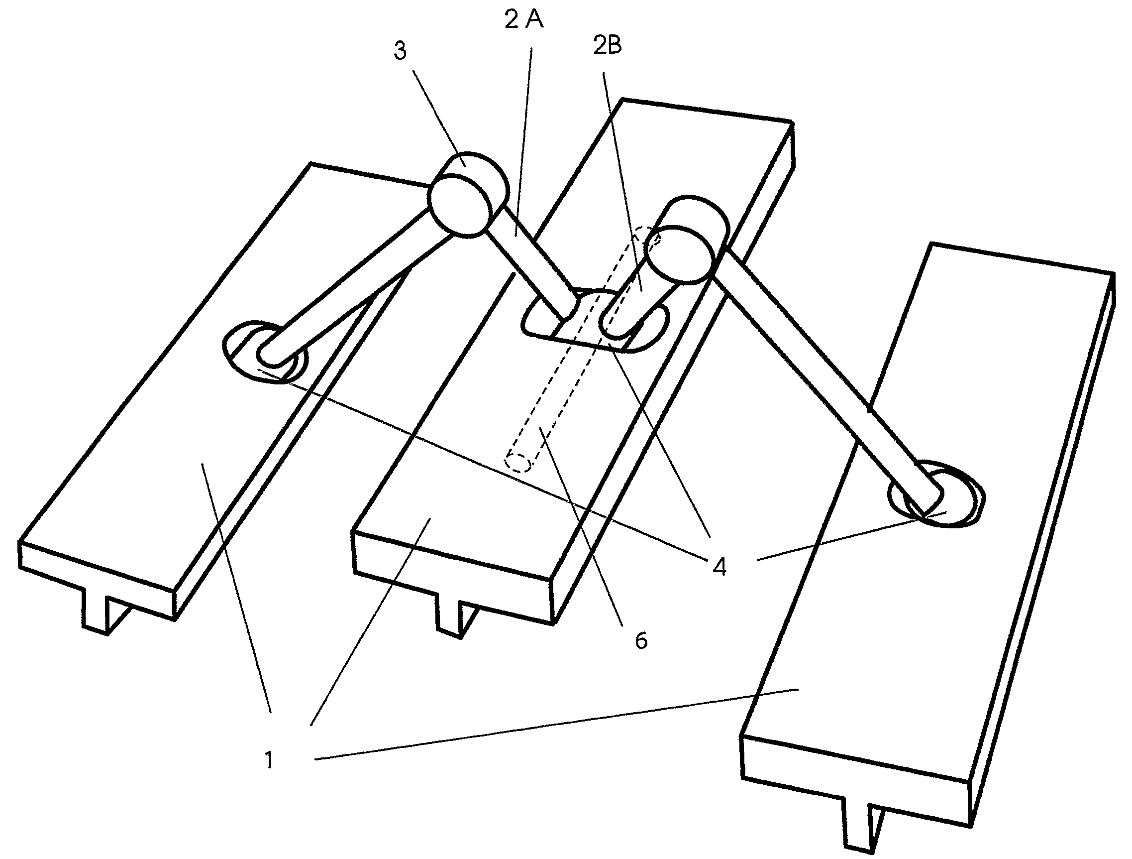
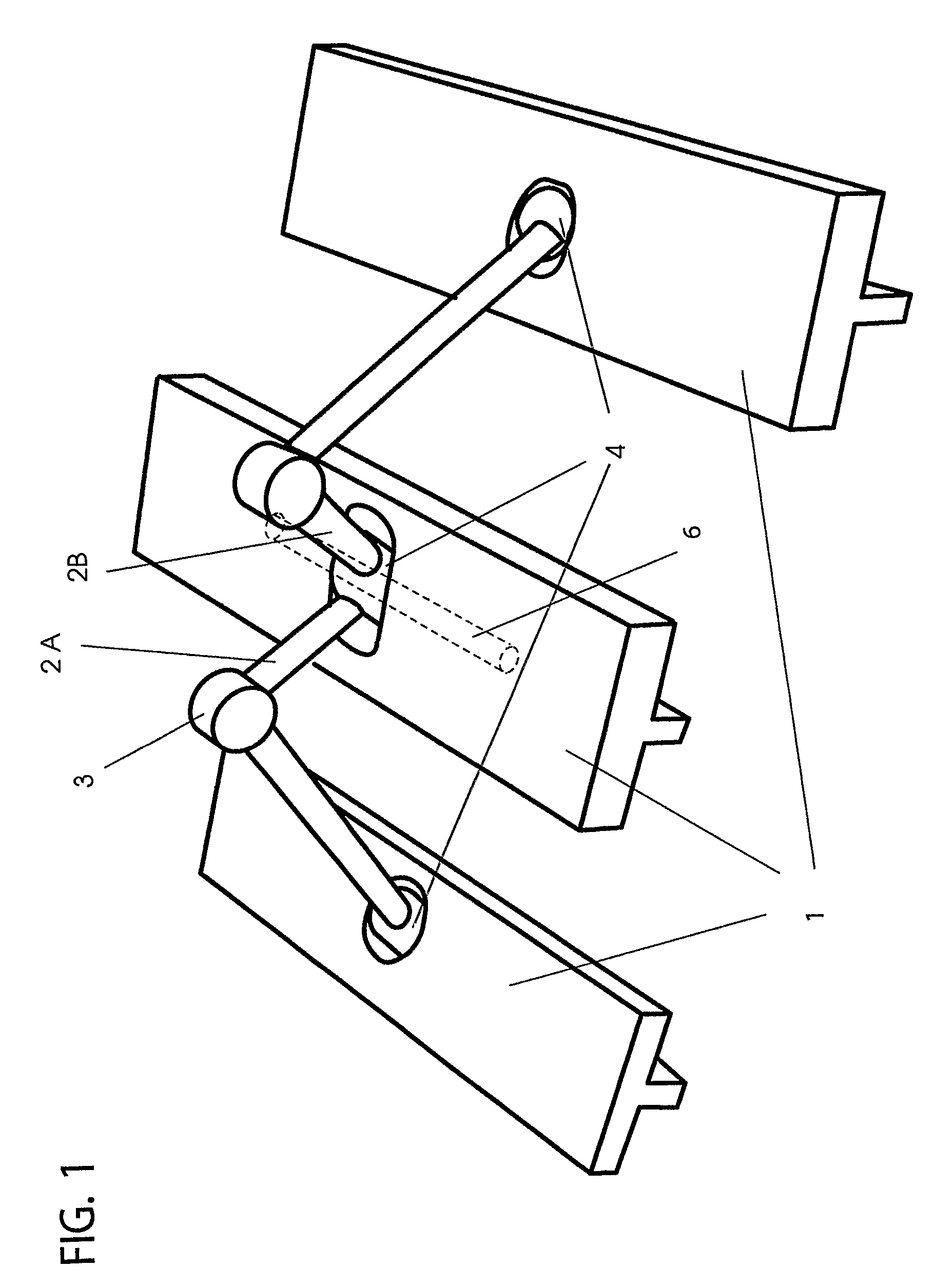
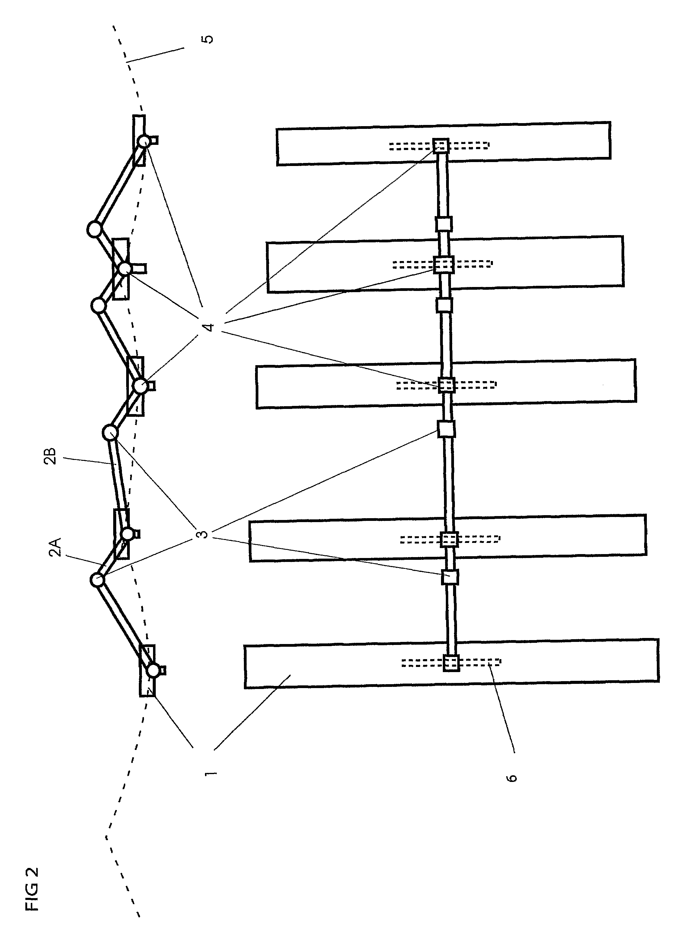
[0019]The water moves each single buoyant element around in its own special phase of the wave, and energy is produced from the forces in the relative motions between each buoyant element and the two next elements (or one at either side) in a chain thereof. The buoyant elements move both vertically and horizontally, and they move in a circular, elliptical or other curvilinear motion whilst rotating about the axes thereof. The phase difference between the motions of each one of these buoyant elements, and also those of other elements, produces this (relative) energy. Yet further, each successive buoyant element assembled within a chain, harvests the energy of a new phase of the wave.

[0020]Insofar as several successive buoyant elements experience different phases of the wave, the wave converter will exploit the relative difference in motion between the buoys in order to harvest the energy of the waves. The wave converter may exploit energy from several wave spectra from several directi...


PUM


Abstract

The special feature of this multiphase and multidimensional wave converter is that it exploits, in an efficient and enduring manner, substantially all of the energy in all waves of the sea, also side waves, and hence is capable of producing large amounts of cheap power. The wave converter comprises at least two buoyant elements (1) connected in a chain of rods (2A, 2B) and joints (3, 4). Each single buoyant element is in a different phase of the wave than that of the others. They will therefore absorb the energy from the relative motion and forces between each set of buoyant elements (1). Each of the elements (1) is capable of moving and pivoting in three dimensions whilst the energy from all these motions is exploited. The energy-producing devices may be comprised of fluid-driving pumps (7, 8, 9) responding to the pivoting of the joints (3,4) and the motion of the rods (2A, 2B). The wave converter absorbs energy from a varying wave spectrum and from all directions. The forces affecting the wave converter are balanced by the various buoyant elements (1), thus avoiding transmitting these forces via mooring. The wave converter provides appreciable economic advantages and durability. It may also operate at any place in the sea and the ocean, at shallow depths as well as at the large depths of the ocean.

Description

CROSS REFERENCE TO RELATED APPLICATION[0001]The present application is the U.S. national stage application of International Application PCT / NO2005 / 000225, filed Jun. 23, 2005, which international application was published on Jan. 19, 2006 as International Publication WO 2006 / 006864. The International Application claims priority of Norwegian Patent Application 20042626, filed Jun. 23, 2004.BACKGROUND OF THE INVENTION[0002]The present invention concerns a wave-powered generator, also termed a wave converter, which converts and exploits most of the energy in the waves in an efficient, simple, inexpensive, robust and durable manner. This completely new and different manner of extracting a lot of energy from the waves provides a solution making it possible to produce clean energy in an inexpensive and lasting manner. This makes the invention feasible, not just technically, but also with respect to commercial requirements. It has been tested in waves, and the description is in agreement w...

Claims


Application Information

Patent Timeline
IPC IPC(8): F03B13/10F03B13/14F03B13/20
CPCF03B13/20F05B2240/40Y02E10/38Y02E10/30
Inventor OTTERSEN, HANS-OLAV
Owner OTTERSEN HANS OLAV
Why Eureka
Try Eureka