Differential amplifier, data driver and display device

a technology of data driver and display device, applied in the direction of differential amplifier, dc-amplifiers with dc-coupled stages, amplifiers with semiconductor devices/discharge tubes, etc., can solve the problems of complex circuit configuration, inability to apply switching control based on figs. 12a and 12b, and achieve the effect of simple circuit arrangemen

Active Publication Date: 2008-10-28
RENESAS ELECTRONICS CORP
View PDF11 Cites 8 Cited by
  • Summary
  • Abstract
  • Description
  • Claims
  • Application Information

AI Technical Summary

Benefits of technology

[0104]In accordance with the present invention, an operational amplifier that is little affected by offset voltage can be provided through a simple circuit arrangement. The operational amplifier is applied to an LCD driver, which is a typical circuit in the video field.

Problems solved by technology

However, there are cases where switching control based upon FIGS. 12A and 12B cannot be applied as is in differential amplifiers other than that described above.
For example, if it is attempted to introduce an operating principle the same as that shown in FIGS. 12A and 12B into the differential amplifier illustrated in FIG. 13, for example, the circuit configuration becomes much more complex and such an arrangement is not realistic.

Method used


Image

  • Differential amplifier, data driver and display device
  • Differential amplifier, data driver and display device
  • Differential amplifier, data driver and display device

Examples


Embodiment Construction

[0118]The present invention will be described in detail with reference to the drawings.

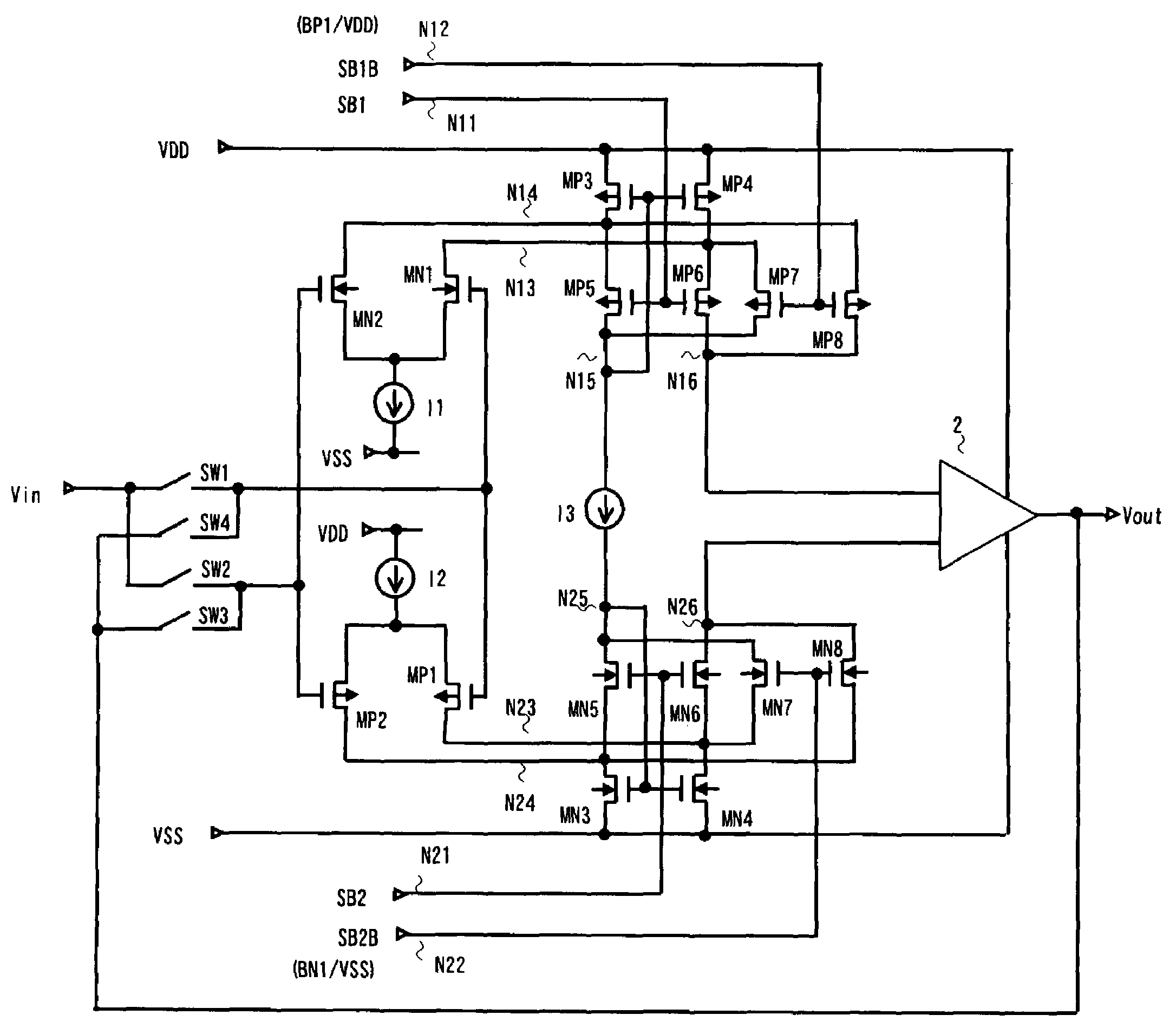
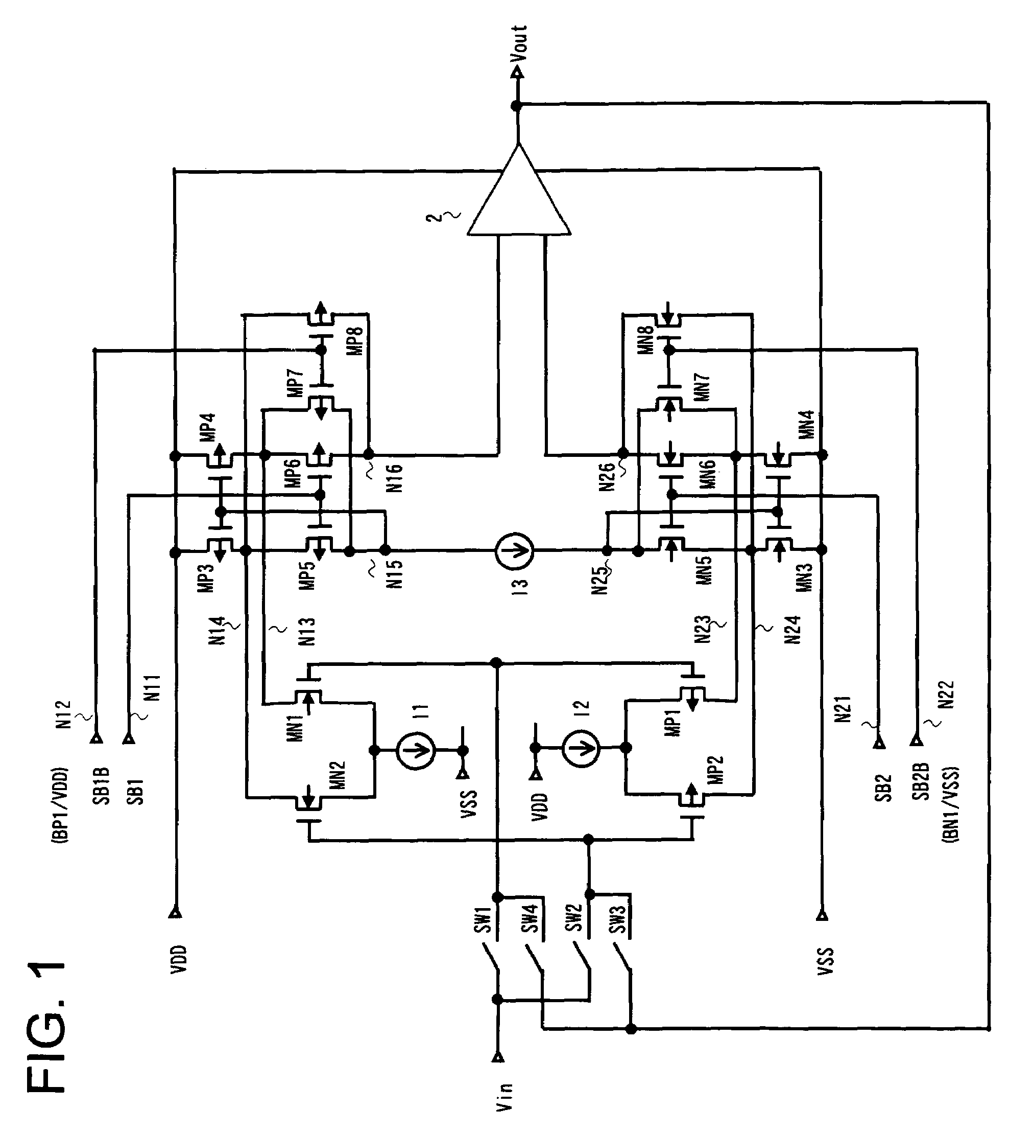
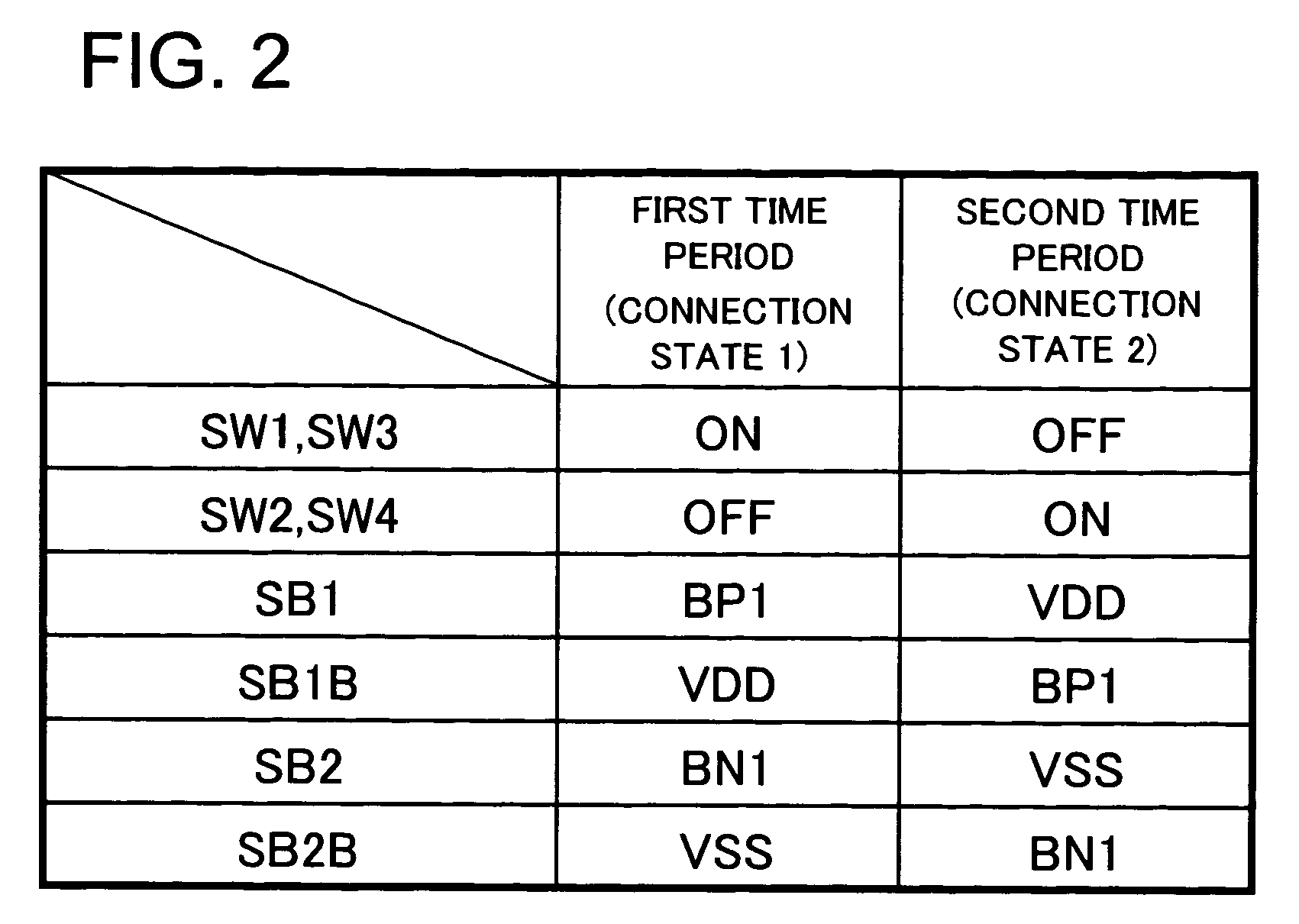
[0119]A differential amplifying circuit according to the present invention comprises: at least one differential pair and a load circuit connected to the differential pair. The load circuit comprises a cascode current mirror circuit that includes a first transistor pair for folding back current from the differential pair, and a cascode section cascode-connected to the first transistor pair. The cascode current mirror circuit is adapted to freely change over the form of connection between the first transistor pair and an input end and an output end of the cascode current mirror circuit to a straight connection or cross connection via the cascode section based upon control signals. More specifically, in the differential amplifying circuit according to the F present invention, the load circuit of at least one differential pair (e.g., NMOS-transistor pair MN1 and MN2) has a cascode current mirror circu...


PUM


Abstract

A differential amplifying circuit that includes a differential pair and a cascode current mirror circuit that forms the load circuit of this differential pair. The cascode current mirror circuit includes a control-terminal-coupled first transistor pair, and second and third transistor pairs that receive first and second bias signals at coupled control terminals, respectively. The second transistor pair is straight-connected between the first transistor pair and the input end and the output end of the cascode current mirror circuit, and the third transistor pair is cross-connected between the first transistor pair and the input end and the output end of the cascode current mirror circuit. The second and third transistor pairs are controlled so as to each be placed in active and inactive states by changing over voltage values of the first and second bias signals, with control being exercised in such a manner that when one of these transistor pairs is in an active state, the other is in an inactive state.

Description

FIELD OF THE INVENTION[0001]This invention relates to a differential amplifier, a data driver and a display device that employs the data driver.BACKGROUND OF THE INVENTION[0002]Liquid crystal display devices (LCDs) characterized by their thin design, light weight and low power consumption have come into widespread use in recent years and are utilized in the display units of mobile devices such as portable telephones (mobile telephones or cellular telephones), PDAs (Personal Digital Assistants) and laptop personal computers. Recently, however, liquid crystal display devices have come to be provided with large-size screens and techniques for dealing with moving pictures have become more advanced, thus making it possible to realize not only mobile applications but also stay-at-home large-screen display devices and large-screen liquid crystal televisions. Liquid crystal display devices that rely upon active matrix drive and are capable of presenting a high-definition display are being u...

Claims


Application Information

Patent Timeline
Patent Type & Authority Patents(United States)
IPC IPC(8): H03F3/45
CPCH03F3/45233H03F2203/45726
Inventor TSUCHI, HIROSHIISHII, JUNICHIRONISHIMURA, KOUICHI
Owner RENESAS ELECTRONICS CORP
Why Eureka
Try Eureka