Tool for insertion and removal of a hearing aid ear wax guard and a method for its use

a technology for hearing aids and tools, applied in metal-working hand tools, recording carriers, applications, etc., can solve the problems of reducing sound reproduction, clogging of acoustic outlet passages, damage to hearing aid electrical components, etc., and achieves improved user comfort, good sound transmission, and low manufacturing cost.

Inactive Publication Date: 2008-10-28
WIDEX AS
View PDF14 Cites 12 Cited by
  • Summary
  • Abstract
  • Description
  • Claims
  • Application Information

AI Technical Summary

Benefits of technology

[0011]As a consequence of the simple design as a short tubular element with a surrounding abutment collar in the end facing inward at the insertion, the ear wax guard according to the invention is inexpensive to manufacture in a large number by molding of the elastically yielding material, which can typically be silicone rubber or a thermoplastic elastomer. A further contribution to this is the positioning of the ear wax retaining barrier in one end of the tubular element which when introduced is led into the acoustic outlet canal. The merely partial opening of this end of the tubular element can be obtained by designing the guard as a kind of screen and thus can assure a good sound transmission.
[0012]Advantageous features and embodiments of the ear wax guard are described below. In a particularly advantageous embodiment, in particular for use in connection with CIC hearing aids, the abutment collar is provided with a convex outside and a concave or faintly conical underside to provide said sealing lip at its peripheral edge. Thus, the user comfort is improved as the ear wax guard essentially follows the outer contour of the aid housing.
[0013]As a consequence of the sealing engagement of the abutment collar of the ear wax barrier against the hearing aid housing, the abutment collar, which can preferably be provided with a relatively thin and soft edge, fitting snugly to the surrounding outside of the housing with a very even transition, it is avoided that when inserting or removing the hearing aid, the abutment collar causes any inconvenience or damage to the ear canal.
[0017]By this applicator design, the insertion of the ear wax guard in the acoustic outlet port and the removal herefrom in connection with the replacement of the ear wax guard can be made in a simple way and with a high degree of security even by weak-sighted users, the different design of the two ends of the applicator for insertion and removal, respectively, contributing to the easy operation.

Problems solved by technology

In in-the-ear hearing aids where the hearing aid housing is placed within the user's ear canal with the acoustic outlet port facing the inner ear and connected to the telephone unit of the hearing aid, it is a well-known problem that the acoustic outlet passage is exposed to contamination with cerumen or ear wax which may lead to clogging of the acoustic outlet passage with consequently reduced sound reproduction.
At worst, there may be a risk for the ear wax to enter the hearing apparatus housing and result in damage to the electrical components of the hearing aid.
As a consequence of the very small dimensions where the acoustic outlet passage has typically a diameter of about 1 mm, the screw plug form entails that insertion and removal of the ear wax guard is a rather difficult operation, especially for weak-sighted hearing aid users, and the inward projections forming a kind of maze in the through-going cavity do not provide full security against migration of ear wax.
Furthermore, the screw plug design cannot be used in in-the-ear hearing aids of the conventional type where the acoustic outlet passage is formed by a short hose or tube member connecting the telephone unit with an acoustic output port in the wall of the hearing aid housing.
As a consequence of the smooth disc-shaped head, the insertion and removal of the plug is also in this case a difficult operation.

Method used


Image

  • Tool for insertion and removal of a hearing aid ear wax guard and a method for its use
  • Tool for insertion and removal of a hearing aid ear wax guard and a method for its use
  • Tool for insertion and removal of a hearing aid ear wax guard and a method for its use

Examples


Embodiment Construction

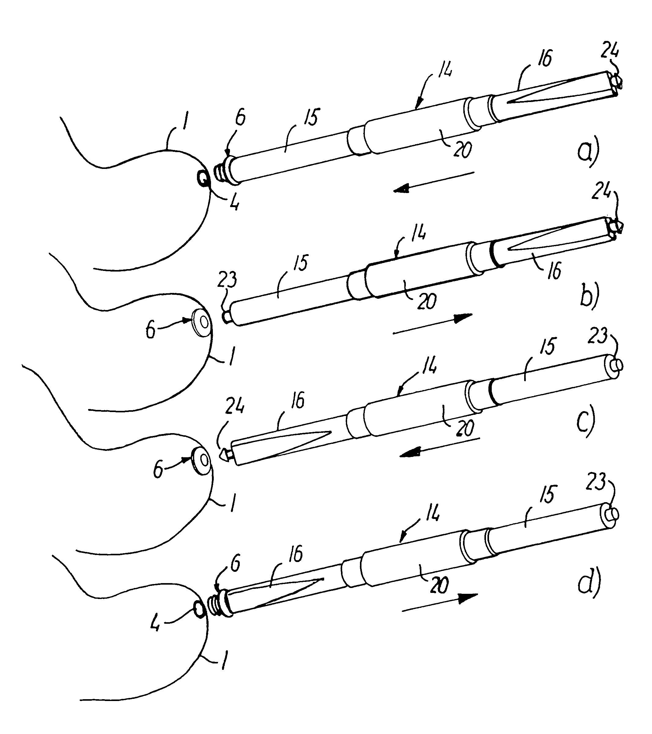
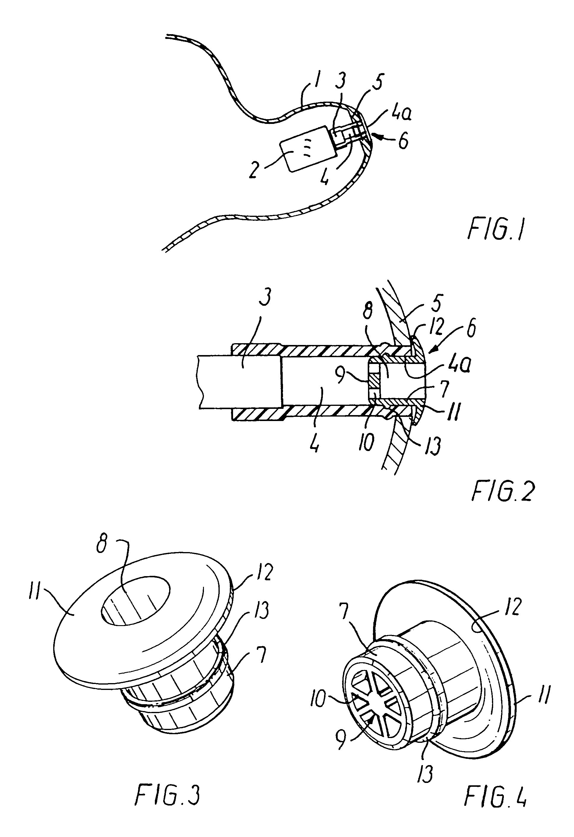
[0038]FIG. 1 shows the portion 1 facing the inner ear, of the housing of an in-the-ear hearing aid designed for position in a user's ear canal. Of the internal components in the hearing aid only an outlet transducer is shown in the form of a telephone unit 2 with an output port 3 which through an acoustic outlet canal 4 formed by a hose member of plastics is connected to an acoustic outlet port 4a designed in an end wall part 5 of the housing portion 1. In order to avoid contamination of the interior of the housing portion 1 with cerumen or ear wax entering through the acoustic outlet canal 4, an ear wax guard 6 is placed herein.

[0039]The embodiment shown in FIGS. 2-4 of the ear wax guard 6 is according to the invention designed as a short, essentially circular cylindrical tubular element 7 with a length and an outer diameter adapted to introduction into the acoustic outlet canal 4 with frictional fit.

[0040]A through-going also essentially circular cylindrical cavity 8 in the tubula...


PUM

PropertyMeasurementUnit
diameteraaaaaaaaaa
inner diameteraaaaaaaaaa
diameteraaaaaaaaaa

Abstract

For the protection of an in-the-ear hearing aid against contamination by ear wax through the acoustic outlet port (34a) or a vent, a replaceable ear wax guard (36) is inserted in the aid and includes an essentially tubular element with a through-going cavity and an abutment collar in one end for sealing abutment against the hearing aid housing (31). For an easy and safe insertion and removal of the ear wax guard (36), an applicator is used, which in one end has a smooth pin for introduction in the through-going cavity of the ear wax guard (36) and in the other end a harpoon-shaped catch member. For mounting of the ear wax guard (36) a hose or tube member serving as acoustic outlet canal (34) is connected to an abutment collar (33) in abutment with the outside of hearing aid. The abutment collar is designed with oversize standard dimensions and adapted to an individually user-adapted hearing aid housing by preparation of its periphery edge.

Description

[0001]This is a divisional of U.S. application Ser. No. 09 / 743,316 filed Jan. 9, 2001 now U.S. Pat. No. 6,795,562, which is a national stage entry of PCT / DK99 / 00022 filed Jan. 15, 1999, both of which are incorporated by reference herein.BACKGROUND OF THE INVENTION[0002]The present invention relates to a replaceable ear wax guard for placement in an opening in a wall part of a housing of an in-the-ear hearing aid designed for positioning in the ear canal, comprising an essentially tubular element partially closed in one end by an ear wax retaining barrier.[0003]In in-the-ear hearing aids where the hearing aid housing is placed within the user's ear canal with the acoustic outlet port facing the inner ear and connected to the telephone unit of the hearing aid, it is a well-known problem that the acoustic outlet passage is exposed to contamination with cerumen or ear wax which may lead to clogging of the acoustic outlet passage with consequently reduced sound reproduction. At worst, th...

Claims


Application Information

Patent Timeline
Patent Type & Authority Patents(United States)
IPC IPC(8): H04R25/00
CPCH04R25/654H04R2460/17Y10T29/4957Y10T29/49572Y10T29/53909Y10T29/49005Y10T29/49575
Inventor GUNNERSEN, FINNTOPHOLM, JAN
Owner WIDEX AS
Why Eureka
Try Eureka