Electrical system wiring diagram generating system, and power supply device and program used for the same

a technology of electrical system and wiring diagram, which is applied in the direction of electric devices, power measurement by pulse modulation, process and machine control, etc., to achieve the effects of preventing trouble and maintenance, analyzing the trouble of the power supply system, and generating easy

Inactive Publication Date: 2008-10-28
FUJI ELECTRIC CO LTD
View PDF54 Cites 6 Cited by
  • Summary
  • Abstract
  • Description
  • Claims
  • Application Information

AI Technical Summary

Benefits of technology

[0014]Applying this configuration, the wiring diagram of the power system can be easily generated. Further, even when connection of the electric device to the power supply are changed, or when a new electric device is added, a new wiring diagram of the power system can be easily generated, according to the change or addition.
[0015]For example, since connecting information of each of the electric devices in the power system can be locally registered, by the dividing unit of the socket or the panel board, just by registering the connecting information, with a downstream list generating means, as confirming, one by one at the location, the connecting state of each of the electric devices in the power supply system, the registration of each of the electric devices is done easily. On the other hand, since there is little possibility to change the connecting information of the panel board or the like, which is located in the upstream side of the power system, the registration of these power supply equipments is usually done at the installation time, with an upstream list generating means. Accordingly, the electrical system wiring diagram generating system generates a wiring diagram of the power system, according to the actual connection in the power system, just by being renewed the registered connecting information of the downstream side of the socket or the panel board, even though the whole connection of the power system is managed continuously.
[0016]As a result, it is easy to check the position, where electric power seems to become insufficient or the like, at the time when the connection of the electric devices is changed, or a new electric device is connected in the power system. Therefore, it is possible to analyze the trouble of the power supply system, prevent trouble and maintenance, enhance the power supply equipments properly according to the connection of the electric devices, and the like.
[0017]Further, it is easy to find out a router and the like, which is not backed up its power by an uninterruptible power supply, and to check the operating state of a communication network under an abnormal condition of the power supply, for example, with a reference to a communication network wiring diagram or the like, and that enables to operate the communication network, with minimizing the influence from the trouble of the power supply system.

Problems solved by technology

As a result, it is easy to check the position, where electric power seems to become insufficient or the like, at the time when the connection of the electric devices is changed, or a new electric device is connected in the power system.

Method used


Image

  • Electrical system wiring diagram generating system, and power supply device and program used for the same
  • Electrical system wiring diagram generating system, and power supply device and program used for the same
  • Electrical system wiring diagram generating system, and power supply device and program used for the same

Examples


embodiment 1

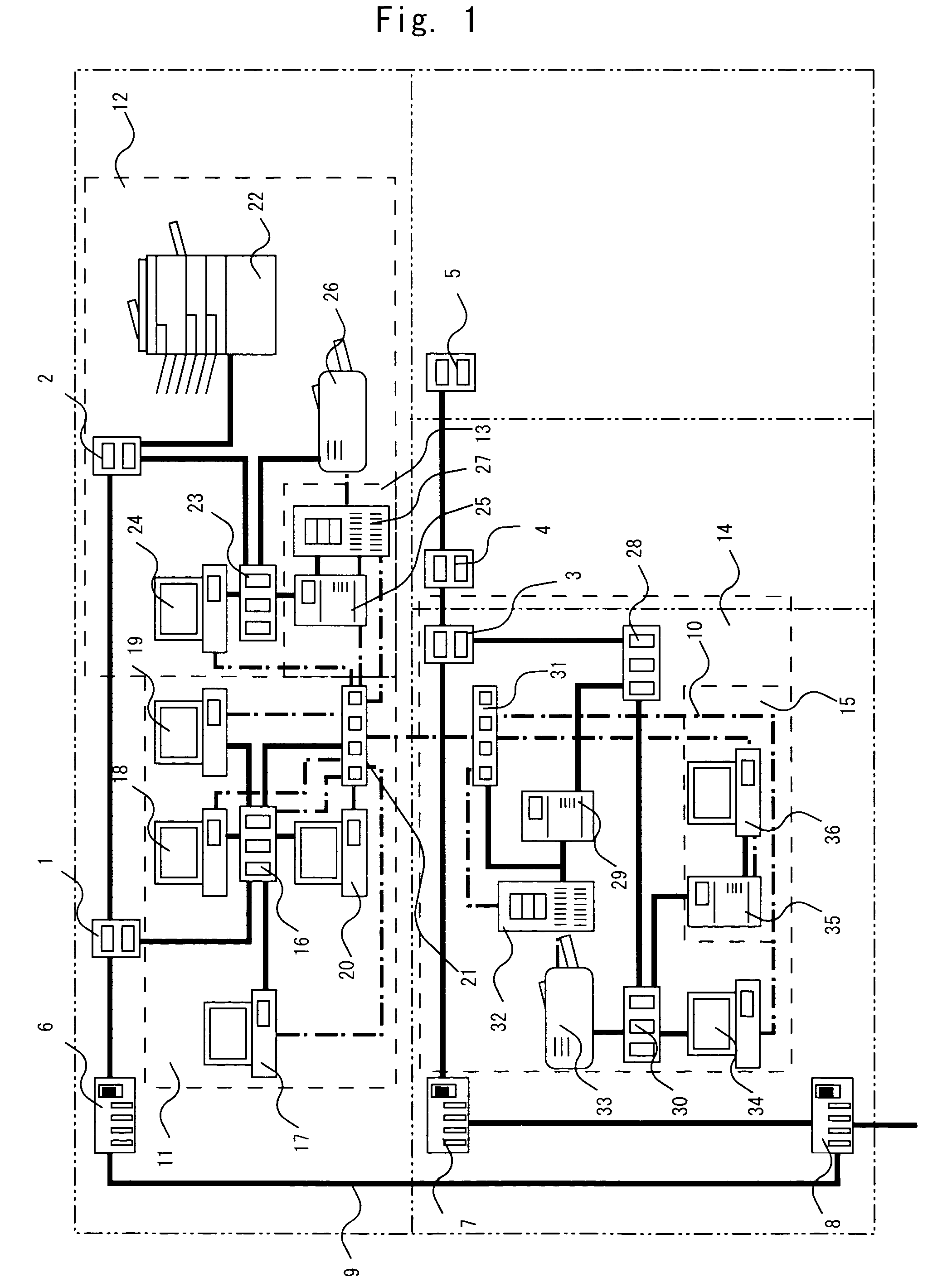
[0031]FIG. 1 is a diagram showing an example of wiring layout of a power system, to which a electrical system wiring diagram generating system, according to a first embodiment of the present invention, is applied. In the drawing, one or two sockets 1, 2, 3, 4, 5 are mounted on a wall in each of four rooms, which are shown by two-dot chain lines. As shown in the drawing, the respective sockets 1, . . . , 5 are connected to two independent panel boards 6, 7 using electric wires, and the two independent panel boards 6, 7 are connected to a main panel board 8 using electric wires. Further, the main panel board 8 is connected to an external power supply using an electric wire. Power supplied from the power supply is distributed and supplied to the sockets 1, . . . , 5, as power supply equipments, via the main panel board 8 and the independent panel boards 6, 7, as power supply equipments.

[0032]It should be noted that, in FIG. 1, thick solid lines indicate power supply lines 9, including ...


PUM


Abstract

Each of connection data 11, . . . , or 15, of the downstream side of a socket 1, . . . , or 5 or a panel board 6, 7, or 8 in a power supply direction, is generated in a tap 16, a UPS 25 and 35, or a terminal 24 or 34, and each of the connection data is transmitted to a electrical system wiring diagram generating terminal 36. Then, a wiring diagram is generated, based on connecting information 91 of the upstream side, which is registered in the generating terminal 36, and the plural connection data of the downstream sides.

Description

TECHNICAL FIELD[0001]The present invention relates to a electrical system wiring diagram generating system, which easily generates a wiring diagram of the power system in buildings, offices, houses, and the like, which can be suitably used, and also relates to a power supply device and a program used for the electrical system wiring diagram generating system.BACKGROUND ART[0002]Recently, so-called office automation has become advanced in buildings, offices, and the like. Therefore, many computer terminals are used in there, and they can transmit / receive data to / from each other via a communication network.[0003]Further, computer terminals also have been spread in houses to use the Internet, besides so-called conventional house appliances such as refrigerators and audio visual devices had already been spread.[0004]In such situations, for example, the following problems have arisen.[0005]Electric power consumption in each office or each house increases, due to the increase of electric ...

Claims


Application Information

Patent Timeline
IPC IPC(8): G05B15/02G01R21/00G01R21/127G01R21/133G05B11/01G06F17/40G06F17/50G06F1/30H02J13/00
CPCG06F1/30G06F17/5077G06F17/509G06F2217/36G06F2217/78G06F30/18G06F30/394G06F2113/16G06F2119/06
Inventor KADOI, HIROKAZUTOGASHI, FUJITAKAMIYAZAKI, AKINORITAKANO, KAZUHIKO
Owner FUJI ELECTRIC CO LTD
Why Eureka
Try Eureka