
Automatic resource sharing between FIFOs

a resource allocation and resource technology, applied in the field of memory device resource allocation, can solve the problems of proliferation of fifo queues on the chip, adversely affecting the performance of the currently running application, waste of memory space, etc., and achieves the effect of reducing the number of clock cycles, facilitating a more precise monitoring of the number, and increasing memory efficiency

Active Publication Date: 2008-10-28
NVIDIA CORP
View PDF2 Cites 27 Cited by
  • Summary
  • Abstract
  • Description
  • Claims
  • Application Information

AI Technical Summary

Benefits of technology

[0006]Accordingly, a need exists to enable dynamic re-allocation of physical buffer space of an electronic device as applications need the memory (e.g., from a de-selected software application to a currently running application). While meeting the above stated need, it would also be advantageous to perform the dynamic re-allocation in a manner that is transparent to the user. What is needed is a dynamic re-allocation system that would efficiently share memory resources across multiple clients that share the FIFO space.
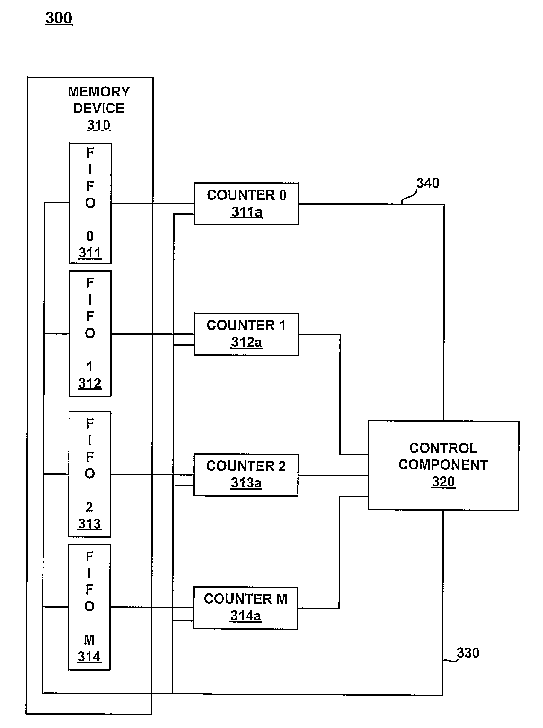
[0009]Furthermore, in embodiments of the present invention, the control component can automatically change the polling interval of the counters associated with the FIFO queues. For example, in one embodiment, if a counter associated with one of the FIFO queues saturates, the control component can reduce the number of clock cycles between polling events. This facilitates a more precise monitoring of the number of times a FIFO queue may be denying a write operation to an application. Embodiments of the present invention may be implemented in software, or in hardware.
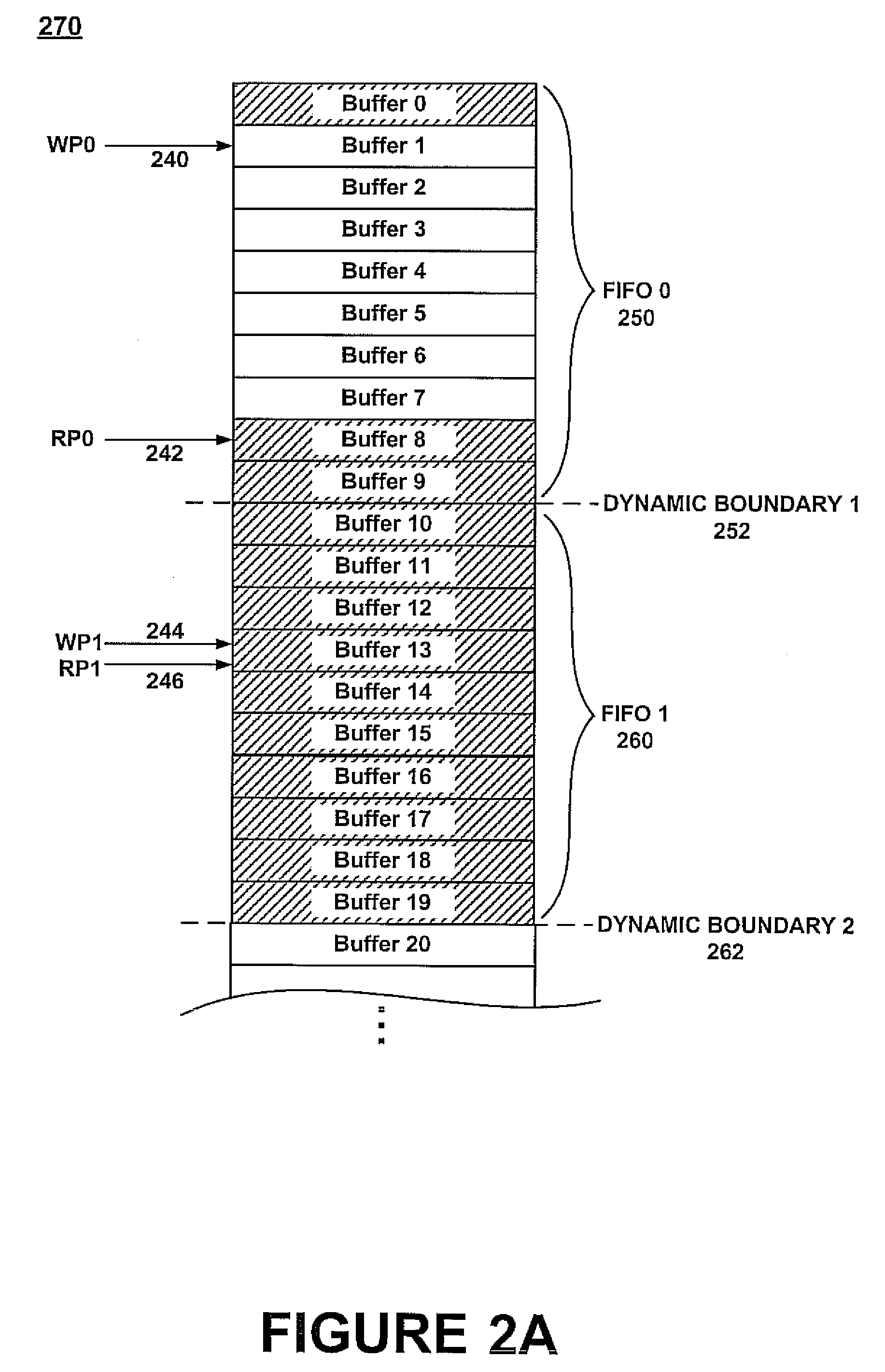
[0010]By allocating more memory to a FIFO that is filling periodically, the embodiments of the present invention provide for increased memory efficiency while being transparent to the clients that share the memory. Embodiments of the present invention advantageously reduce system back-pressure by dynamically resizing FIFO sizes in response to real-time memory usage as periodically monitored.

Problems solved by technology

If an application is denied a write operation, it can adversely affect the performance of the currently running application when the FIFO acts as a bottleneck.
However, oversizing the FIFO queues in this manner wastes memory space which might be more productively allocated to the currently running application.
Additionally, as more functionality is built into devices and chip designers strive to ensure that no client is denied access to data, the number of FIFO queues on the chip is proliferating, thus consuming even more memory space and power.

Method used


Image

  • Automatic resource sharing between FIFOs
  • Automatic resource sharing between FIFOs
  • Automatic resource sharing between FIFOs

Examples


Embodiment Construction

[0019]Reference will now be made in detail to embodiments of the present invention, examples of which are illustrated in the accompanying drawings. While the present invention will be described in conjunction with the following embodiments, it will be understood that they are not intended to limit the present invention to these embodiments alone. On the contrary, the present invention is intended to cover alternatives, modifications, and equivalents which may be included within the spirit and scope of the present invention as defined by the appended claims. Furthermore, in the following detailed description of the present invention, numerous specific details are set forth in order to provide a thorough understanding of the present invention. However, embodiments of the present invention may be practiced without these specific details. In other instances, well-known methods, procedures, components, and circuits have not been described in detail so as not to unnecessarily obscure aspe...


PUM


Abstract

Embodiments of the present invention recite a method and system for allocating memory resources. In one embodiment, a control component coupled with a memory device determines that a data buffer adjacent to a boundary of a first FIFO queue does not contain current data. The control component also determines that a second data buffer of a second FIFO queue adjacent to the boundary does not contain current data. The control component then automatically shifts the boundary to include the second data buffer in the first FIFO queue.

Description

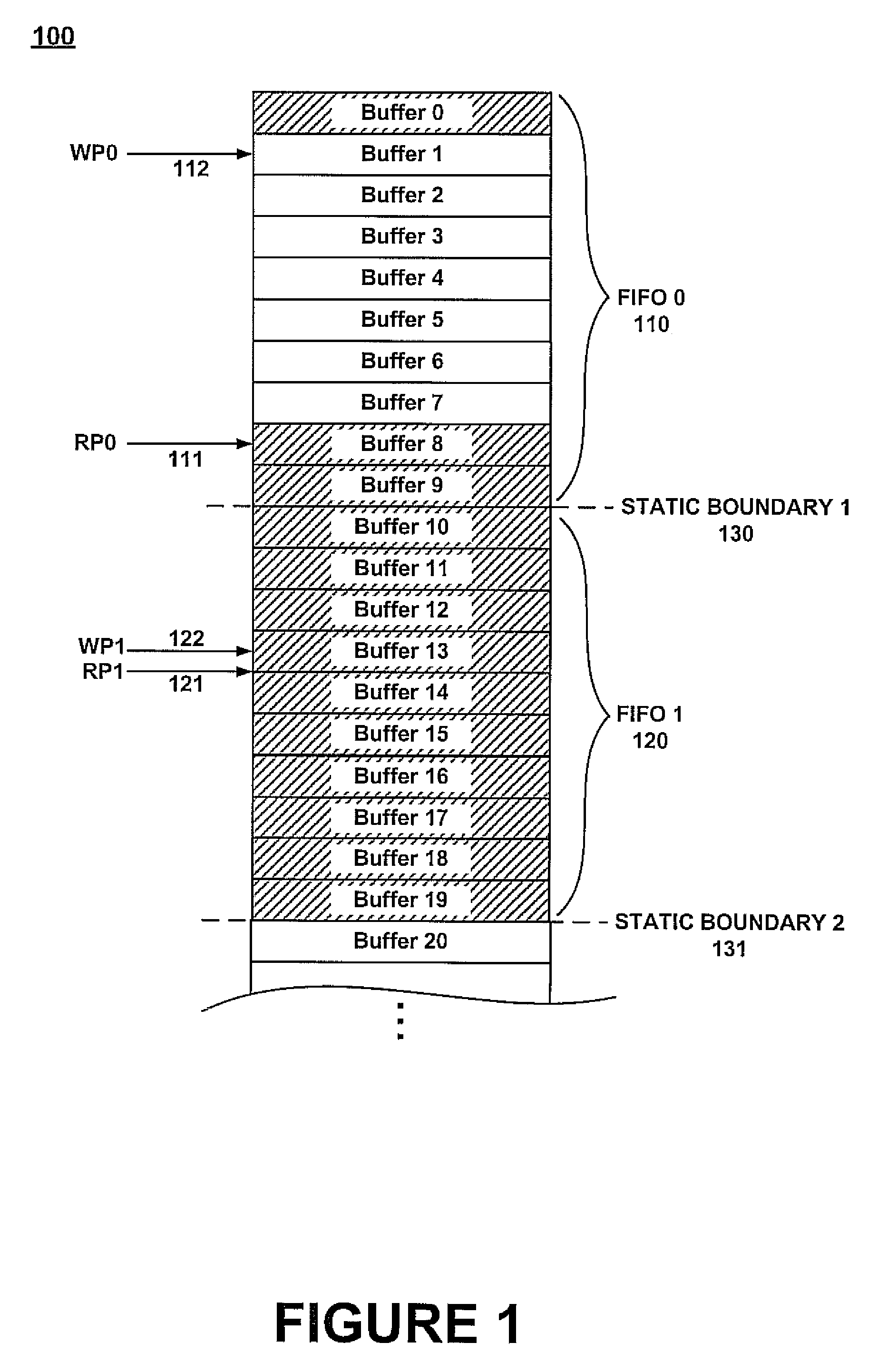
FIELD OF THE INVENTION[0001]Embodiments of the present invention are related to the field of resource allocation in memory devices.BACKGROUND OF THE INVENTION[0002]In many current electronic devices, a discrete portion of main memory may be allocated to each of the programs running on the device. FIG. 1 shows one implementation of an exemplary prior art shared memory space 100. In FIG. 1 memory space 100 comprises a plurality of memory buffers (e.g., buffer 0-buffer 20) which are grouped to form 2 first-in first-out (FIFO) data queues, FIFO 0 and FIFO 1 are adjacent to and separated by a static boundary 1 (e.g., 130) which is indexed at a value of 10. Also shown in FIG. 1 is a static boundary 2 (e.g., 131) which separates FIFO 1 from the next adjoining FIFO and which is indexed at a value of 20. Also shown in FIG. 1 are a read pointer 0 (RP0) 111 which indicates that the next buffer in FIFO 0 into which data will be accessed, and a write pointer 0 (WP0) 112 which indicates the next ...

Claims


Application Information

Patent Timeline
Patent Type & Authority Patents(United States)
IPC IPC(8): G06F12/00
CPCG06F5/06G06F2205/063
Inventor STEINBUSCH, OTTO L.
Owner NVIDIA CORP
Learn More