Needle threading machine

a needle threading machine and needle threading technology, applied in the field of needle threading machines, can solve the problems of loss of work time, inconvenient, unavoidable need, etc., and achieve the effect of reducing defective needle threading work and enhancing productivity

Inactive Publication Date: 2008-11-04
INBRO
View PDF11 Cites 7 Cited by
  • Summary
  • Abstract
  • Description
  • Claims
  • Application Information

AI Technical Summary

Benefits of technology

[0006]Accordingly, it is an aspect of the present invention to provide a needle threading machine, in which a thread is stably hooked on a hook, thereby reducing a defective needle threading work and enhancing productivity.

Problems solved by technology

In a sewing machine, an automatic embroidering machine or the like, there is unavoidably needed a needle threading work that passes a thread through an eye of a needle provided in a lower part of a head stem in order to change an upper thread.
Such a needle threading work takes much time and is inconvenient.
Particularly, the thread is frequently changed in the case of the automatic embroidering machine that uses various colored threads, thereby causing the loss of work time.
Therefore, friction between the thread passing through the eye of the needle and the hook causes damage on the thread.
Also, because the hook is repeatedly deformed, the durability of the hook is decreased and the hook is damaged.
Further, the needle threading work is performed in the state that the thread is unstably hooked on the hook, thereby causing the defective needle threading work and decreasing productivity

Method used


Image

  • Needle threading machine
  • Needle threading machine
  • Needle threading machine

Examples


first embodiment

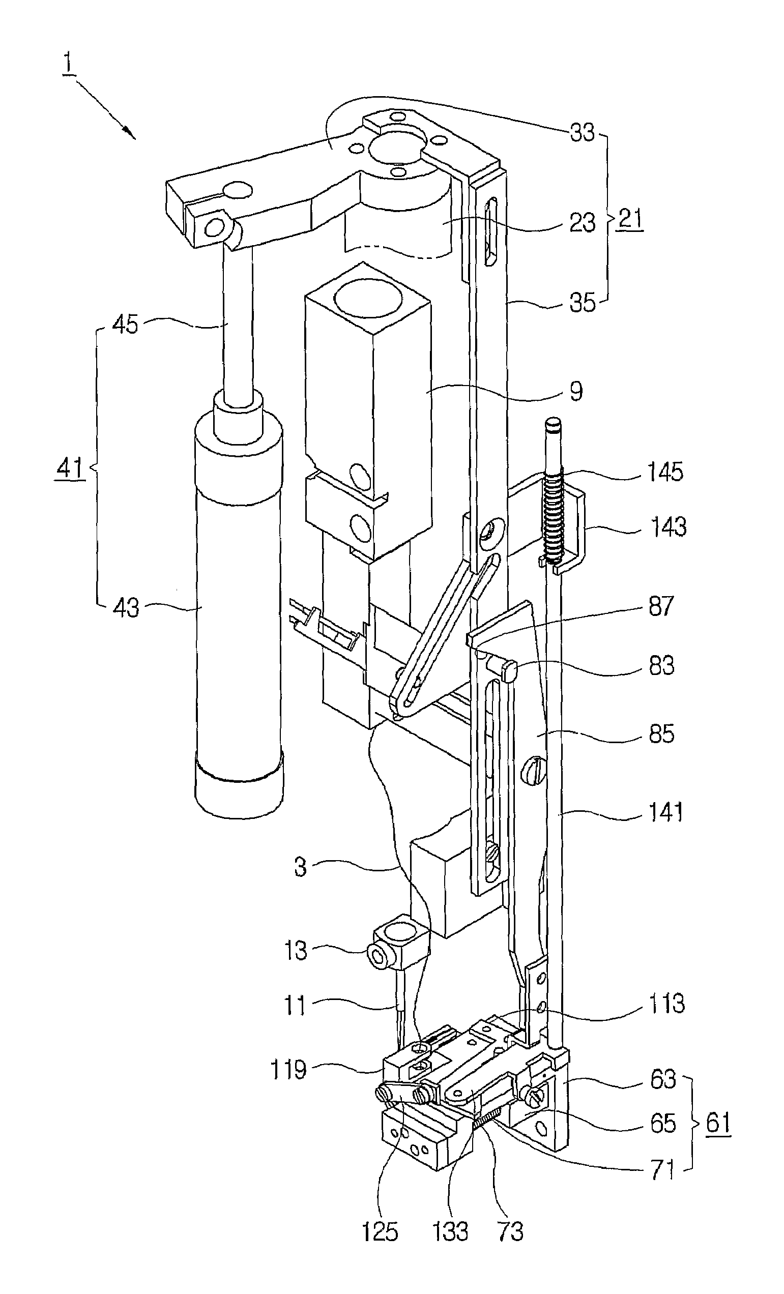
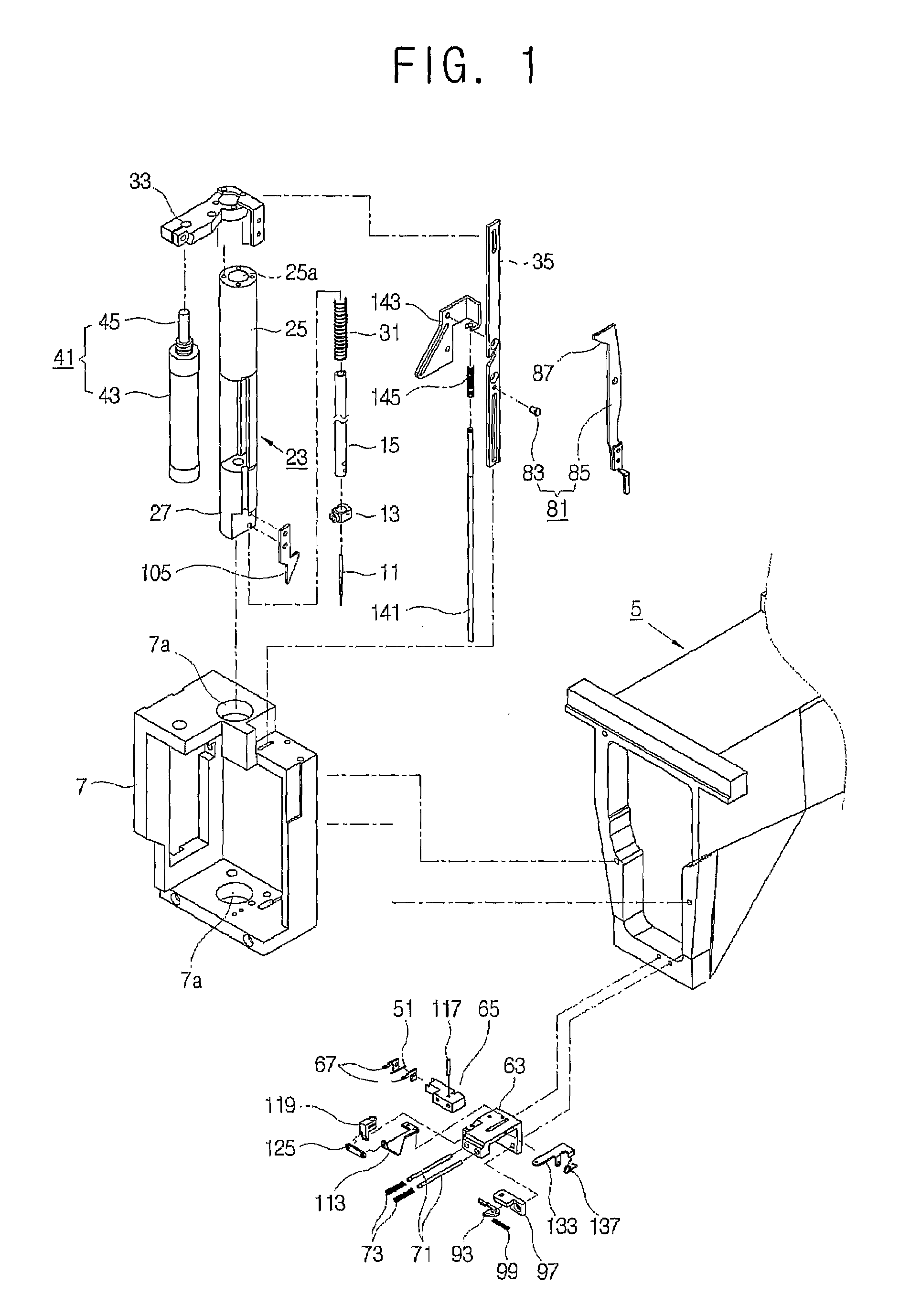
[0027]As shown in FIGS. 1 and 2, a needle threading machine 1 according to the present invention includes a needle 11 threaded with a thread supplied from a thread supplying unit 9 along a predetermined thread guiding path (not shown).

[0028]The needle 11 reciprocates within a predetermined sewing work section passing through a needle plate (not shown), and is mounted to an end of a needle bar 15 by a needle holder 13.

[0029]The needle bar 15 is shaped like a tube-body, and controllably connected to a needle bar driver (not shown) reciprocating within a predetermined section by a clutch (not shown). Thus, the needle bar 15 is connected to the needle bar driver through the clutch, so that the needle 11 mounted to the end of the needle bar 15 reciprocates within the sewing work section by the reciprocating operation of the needle bar driver, thereby performing a sewing operation.

[0030]Meanwhile, the needle threading machine 1 according to an embodiment of the present invention includes ...

second embodiment

[0088]Further, the needle threading machine 1′ according to the present invention includes the lifting rod 141 formed with a groove 141a at an upper part thereof.

[0089]The lifting rod 141 is provided with a lifting clutch 151, so that the lifting operation of the lifting rod 141 is controlled. The lifting clutch 151 includes a protrusion 153 locked to and released from the groove 141a, and an extended part 155 extended from the protrusion 153. Also, the lifting clutch 151 is coupled to the supporting frame 5 by a clutch elastic member (not shown), so that the lifting clutch 151 reciprocates transversely to the lifting direction of the lifting rod 141.

[0090]The upper part of the auxiliary bracket 143 is provided with a clutch operator 161 to operate the lifting clutch 151. The clutch operator 161 is formed with a clutch cam profile 163 inclined downward so that the extended part 155 moves being in contact with and spaced from the clutch cam profile 163. When the lifting rod 141 is li...


PUM


Abstract

Disclosed is a needle threading machine of putting a thread through an eye of a needle provided in a sewing machine, the needle treading machine comprising a thread supplying unit supplying the thread along a predetermined thread guiding path; a thread catcher comprising a hook to hook the thread, and a hook supporter extended from the hook and supporting the hook; a thread catcher driver driving the thread catcher to reciprocate allowing the hook to be inserted in and return from the eye of the needle; and a thread guiding unit hooking the thread supplied from the thread supplying unit on the hook passed through the eye of the needle. Thus, the present invention provides a needle threading machine, in which a thread is stably hooked on a hook, thereby reducing a defective needle threading work and enhancing productivity.

Description

FIELD OF THE INVENTION[0001]The present invention relates to a needle threading machine for a sewing machine, and more particularly, to a needle threading machine having an improved structure of hooking a thread on a hook.BACKGROUND ART[0002]In a sewing machine, an automatic embroidering machine or the like, there is unavoidably needed a needle threading work that passes a thread through an eye of a needle provided in a lower part of a head stem in order to change an upper thread.[0003]Such a needle threading work takes much time and is inconvenient. Particularly, the thread is frequently changed in the case of the automatic embroidering machine that uses various colored threads, thereby causing the loss of work time.[0004]Accordingly, there has been disclosed a needle threading machine in Korean Patent Application No. 2000-52077. In this needle threading machine, a hook is provided in the end of a thread catcher and holds the thread. Further, the thread catcher is reciprocated betw...

Claims


Application Information

Patent Timeline
Patent Type & Authority Patents(United States)
IPC IPC(8): D05B87/02D05B85/00
CPCD05B87/02
Inventor PARK, HAM-KYUPARK, IL-GYU
Owner INBRO
Why Eureka
Try Eureka