Dual fuel engine

a fuel engine and dual fuel technology, applied in the direction of fuel supply apparatus, fuel system, electrical control, etc., can solve the problems of time-consuming, complex and expensive conversion of conventional diesel engines, and the cost of conventional conversion, particularly for a large diesel engine, is in the region of £28,000, and achieves high combustion thermal output, easy to adapt to different conditions, and the effect of preventing engine versatility

Inactive Publication Date: 2008-11-04
INTELLIGENT DIESEL SYST
View PDF15 Cites 48 Cited by
  • Summary
  • Abstract
  • Description
  • Claims
  • Application Information

AI Technical Summary

Benefits of technology

[0012]However, a fundamental disadvantage of the invention described in this patent is the predetermined nature of the operating characteristics necessitated by the direct mechanical link between the LPG regulator (which is a valve in the main embodiment) and the governor of the diesel engine. For instance, under a particular load, the governor of the engine will necessarily operate in a particular manner causing the regulator to open or close to a predetermined extent. Accordingly, the system proposed in the U.S. Patent is inflexible.
[0013]A further disadvantage of this invention is the fact that the LPG is mixed with the incoming air flow in a plenum ring prior to entry of the air into the cylinders of the engine. This further precludes versatile operation of the engine.SUMMARY OF INVENTION
[0014]It is an object of the invention to provide a dual fuel engine and management system therefor which is flexible, can be easily adapted to different types of dual fuel combinations (e.g. diesel / LPG, diesel / CNG, and diesel / other liquid or gaseous combustive material giving high combustion thermal output), and which is capable of significantly reducing the overall emissions of the engine over a wide operating profile.
[0015]According to a first aspect of the invention there is provided a dual fuel engine, said engine supplied with diesel fuel and at least one secondary fuel, said engine including one or more cylinders in which one or more pistons reciprocate, each of said one or more cylinders being provided with diesel injection means for injecting the diesel fuel into the cylinder during an appropriate stroke of the piston and at least one air inlet valve, said valve moving to an open condition during said appropriate stroke of the piston to permit air flow therethrough, characterised in that each cylinder of the engine is further provided with secondary fuel injection means for injecting the secondary fuel into the cylinders, the secondary fuel injection means being independent of the diesel fuel injection means and air inlet valves.
[0016]By providing the secondary fuel injection means independent to and separate from the diesel fuel injection means, this provides the engine with greater flexibility and increases the ease with which an engine can be converted to utilise other fuels in addition to diesel. Control of the operation of the secondary fuel injection means is also typically independent to that of the diesel injection means, thereby providing the engine with greater flexibility to changing engine operating conditions.
[0017]Preferably the secondary fuel injection means are controlled to introduce the secondary fuel in the one or more cylinders on the appropriate stroke of the piston reciprocating therein.

Problems solved by technology

Currently, it is generally the case that most conventional diesel engine conversions are time consuming, elaborate and expensive.
It is this latter requirement for heat that necessitates a delay between initially starting the engine (which causes a heater to operate) and firing the engine, i.e. causing the driveshaft on which the pistons are mounted to rotate.
A conventional conversion, particularly for a large diesel engine such as might be provided in a locomotive or articulated lorry may cost in the region of £28,000.
However, a fundamental disadvantage of the invention described in this patent is the predetermined nature of the operating characteristics necessitated by the direct mechanical link between the LPG regulator (which is a valve in the main embodiment) and the governor of the diesel engine.
A further disadvantage of this invention is the fact that the LPG is mixed with the incoming air flow in a plenum ring prior to entry of the air into the cylinders of the engine.
This further precludes versatile operation of the engine.

Method used


Image

  • Dual fuel engine
  • Dual fuel engine
  • Dual fuel engine

Examples


Embodiment Construction

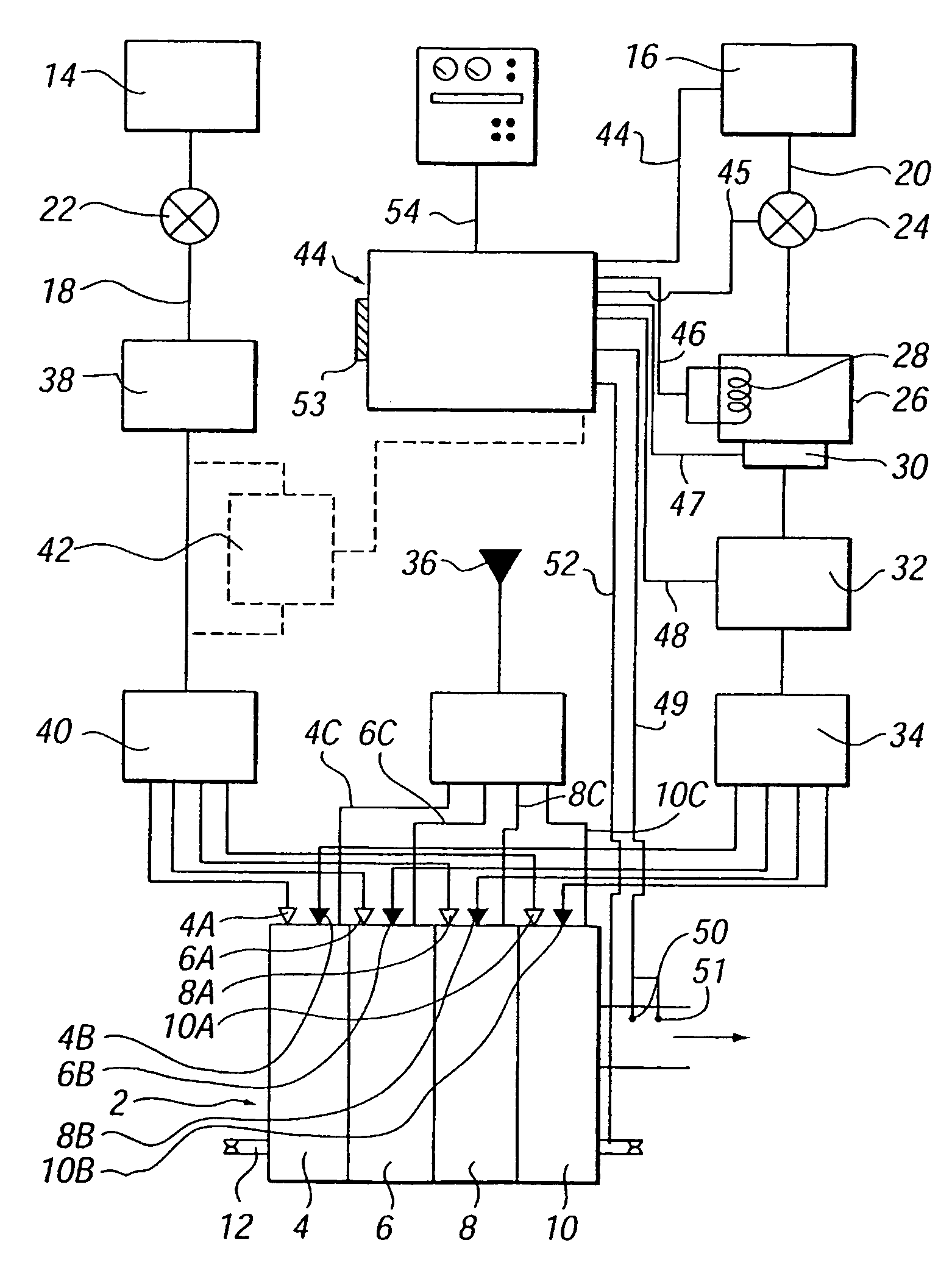
[0066]Referring to FIGS. 1 and 4, there is provided an engine 2 comprising four cylinders 4, 6, 8, 10 in which pistons are disposed (not shown) mounted on a drive shaft 12 by which power is delivered from the engine. Each of the cylinders is provided with a pair of injectors 4A, 4B, 6A, 6B, 8A, 8B, 10A, 10B, and air inlets 4C, 6C, 8C, 10C.

[0067]The engine is supplied with two different fuels from separate tanks 14, 16, and the fuel is delivered from these tanks to the injectors 4A, 4B, 6A, 6B, 8A, 8B, 10A, 10B via supply pipes 18, 20. Emergency shut off valves 22, 24 are disposed proximate the tanks for obvious purposes.

[0068]The tank 16 is adapted to contain slightly pressurised LPG (to liquefy same), and this LPG is delivered firstly to a vaporiser unit 26 having a heater 28 therein. A diaphragm 30 is also provided in this vaporiser. Thereafter, the LPG flows along the supply pipe 20 to a flow control unit (FCU) 32 which can also be adjusted to alter the volume of LPG allowed to p...


PUM


Abstract

A dual fuel engine (2) is provided which is supplied with diesel fuel and at least one secondary fuel, such as LPG. The engine (2) has a plurality of cylinders (4, 6, 8, 10) in which pistons reciprocate. Each cylinder has diesel injectors (4A, 6A, 8A, 10A) for injecting the diesel fuel into the cylinder during an appropriate stroke of the piston and an air inlet valve (4C, 6C, 8C, 10C) which opens during the appropriate stroke of the piston to permit air flow therethrough. Each cylinder is further provided with LPG injectors (4B, 6B, 8B, 10B) for injecting the secondary fuel into the cylinders. The LPG injectors are independent to and separate from the diesel fuel injectors. The LPG and diesel fuel injectors are also independently controlled.

Description

BACKGROUND OF THE INVENTION[0001]1. Field of Invention[0002]This invention relates to a dual fuel engine, and more specifically to a method for converting a conventional diesel engine to one which is capable of receiving both diesel and at least one second fuel, which is most commonly liquid petroleum gas (LPG) or less commonly compressed natural gas (CNG). The invention also relates to and is to be considered as extending to a dual fuel engine or multi-fuel engine which operates in a particular manner as hereinafter described.[0003]2. Background of Invention[0004]Although the following description is provided with exclusive reference to the conversion of conventional diesel engines to engines which are capable of receiving both diesel and LPG as the main combustive fuel components, the skilled reader will appreciate that the following invention can easily be adapted to allow for conversion of conventional diesel engines to permit them to utilize a wide variety of different gases, a...

Claims


Application Information

Patent Timeline
Patent Type & Authority Patents(United States)
IPC IPC(8): F02B7/00F02B3/06F02D19/08F02D41/00F02D41/24F02M21/02F02M21/06
CPCF02D19/0628F02D19/0647F02D19/0684F02D41/0027F02D41/2429F02D19/061F02D19/0678F02D19/0692F02D19/081F02B3/06F02B2201/064F02B2275/14F02D41/0025F02D41/2441F02M21/06Y02T10/36Y02T10/123Y02T10/12Y02T10/30F02D19/066
Inventor SHUTE, COLIN ROBERT
Owner INTELLIGENT DIESEL SYST
Why Eureka
Try Eureka