
Quick connect coupling

a hose coupling and quick technology, applied in the direction of hose connection, pipe-joint, adjustable joint, etc., can solve the problems of affecting the cost of producing such couplings, affecting the economic viability of such couplings, and a greater opportunity for inadvertent and sudden disconnects, so as to improve safety and quick connection

Active Publication Date: 2008-11-04
THE GATES CORP
View PDF29 Cites 22 Cited by
  • Summary
  • Abstract
  • Description
  • Claims
  • Application Information

AI Technical Summary

Benefits of technology

The present invention is an improved quick connect and quick to disconnect hose coupling with safety improvements. It has a female portion with a dual function frustoconical portion that compresses the sealing element and clip during connection and disconnection. A sleeve is also included to capture the clip. The invention retains the benefits of quick connect and quick to disconnect couplings while improving safety.

Problems solved by technology

Historically, the considerations that have driven the design of such couplings have included complexity of port design, effecting machineability, complexity of stem design, complexity and location of sealing elements such as o-rings or other shape of seals, complexity and location of locking components such as clips of various shapes, total number of components needed to complete the coupling, and interplay of the geometry of the port and the stem.
All of these have greatly affected the cost of producing such couplings which impacts greatly upon their economic viability.
The quick disconnect characteristic of such couplings necessarily give rise to a greater opportunity for inadvertent and sudden disconnects, with grave results.
Unexpected impacts upon quick to disconnect couplings or maintenance in such difficult quarters can increase the likelihood of inadvertent disconnects.
Inadvertent disconnects on pressurized systems can lead to damaged or broken machines, destroyed premises, severe injuries to maintenance or other workers, or even death, such as through unexpected machinery movement or spray of very hot fluids at high pressure.
However, the disclosed stem is more complex including all sealing and locking components.
Further, the locking component is intricate and relatively complex.
The complexity and additional components would increase the cost of the coupling.
This causes the port to compress the locking component.
However, both the use and shape of the stop member leaves substantial opportunity for the coupling to experience disastrous inadvertent disconnection.
First, there is no way to ensure that the stop member will be properly installed on the coupling during the entire time of its deployment.
In such a condition the coupling would no longer be resistant to inadvertent disconnection.
Once again, the coupling would no longer be resistant to inadvertent disconnection.
Safety is also compromised by the existence of such a rigid loop in many industrial or heavy machinery environments.
It can be a direct source of damage or injury through the entanglement of debris, tools, clothing, hair or fingers.
Further, it is not inconsequential that every time the coupling is to be disconnected, the metal loop, comprising the stop member, is removed to become lost as hazardous debris.

Method used


Image

  • Quick connect coupling
  • Quick connect coupling
  • Quick connect coupling

Examples


Embodiment Construction

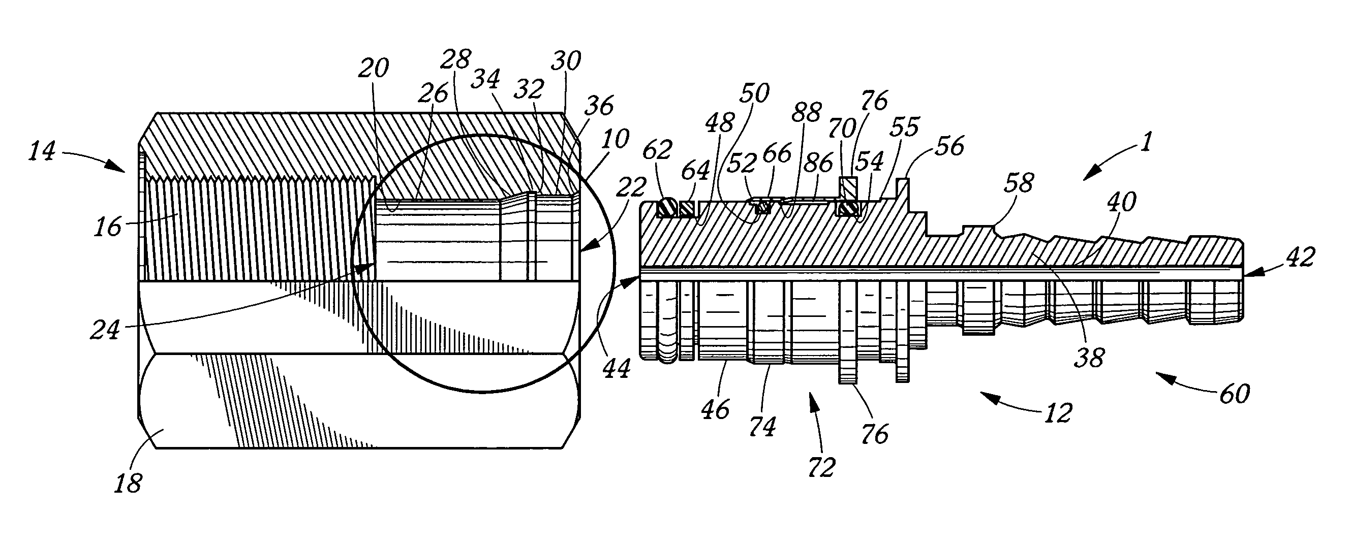
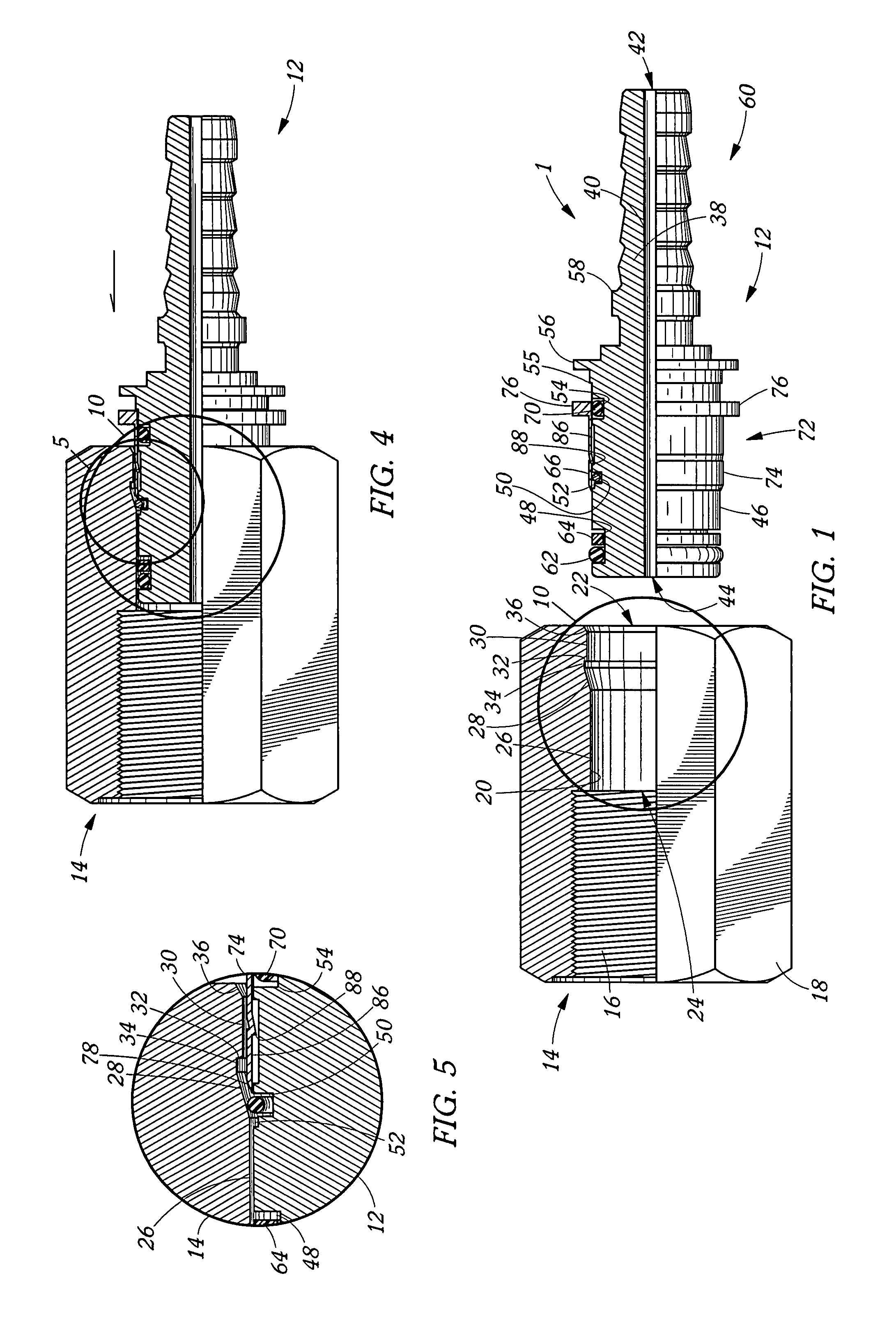
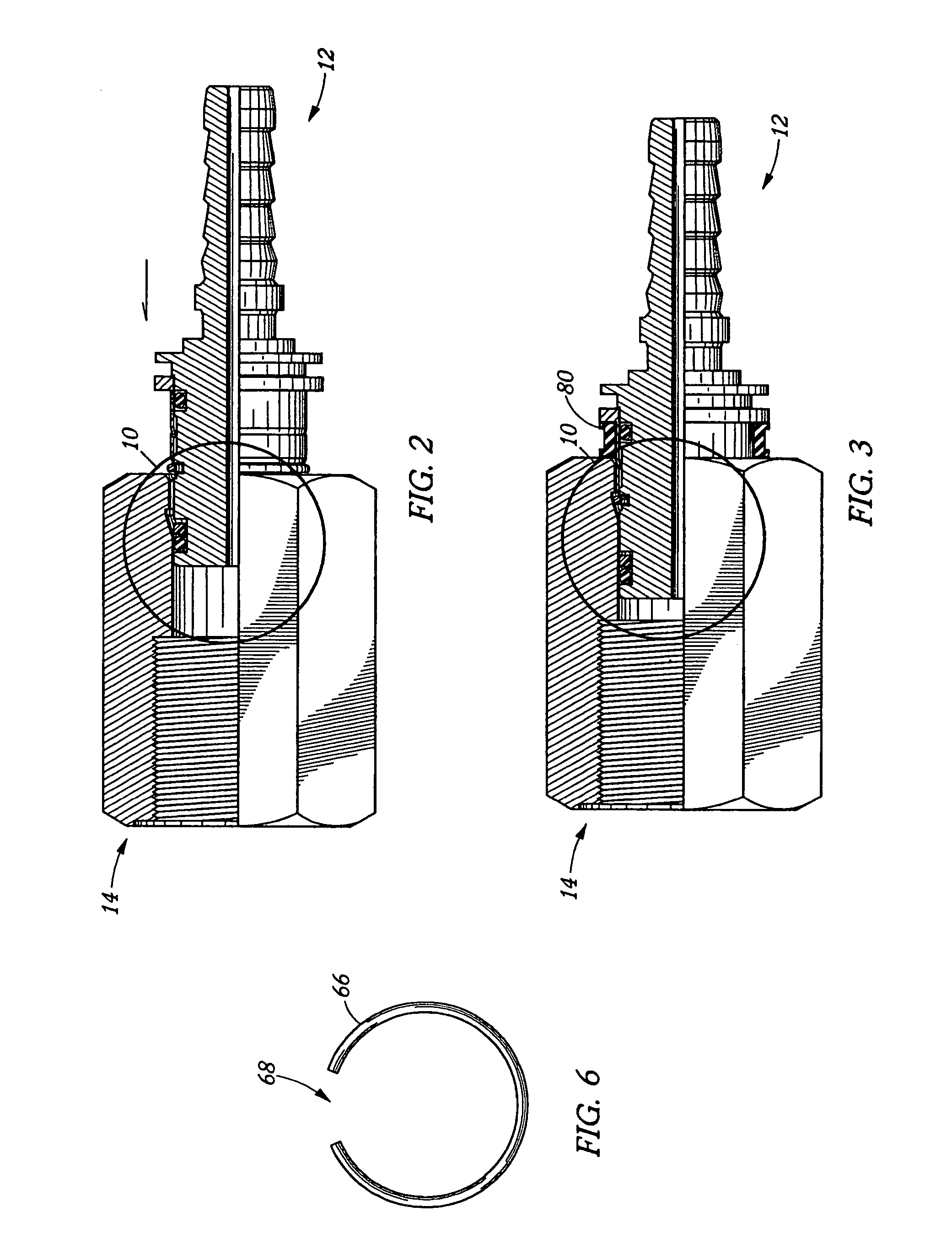
[0025]Referring to FIG. 1, a preferred embodiment of this quick connect coupling 1 of the instant invention includes female portion or port 10 and hose stem 12. The female portion or port 10 is illustrated as part of an adapter 14 having threads 16 and formed with wrenching flats 18, as one contemplated embodiment and for convenience of illustration. Commonly, port 10 is expected to be machined into the body of a fixture, machine or equipment not depicted. For those instances where port 10 is formed into an adapter 14, adapter 14 provides the base for port 10. For those instances where port 10 is formed into a fixture, machine or equipment, these provide the base. Port 10 has an interior surface 20 defining an inlet opening 22, an outlet opening 24, a fluid passage 26, a first frustoconical ramp 28, a first cylinder 30, annular wall 32, second frustoconical ramp 36, and optionally second cylinder 34. First frustoconical ramp 28 is a dual function ramp serving functions in both the c...


PUM


Abstract

A quick to connect and quick to disconnect fluid coupling has a clip, a male portion having an annular groove adapted to receive the clip, a female portion, and a sealing element. It is improved by the female portion having a dual function frustoconical portion adapted to compress the sealing element during joinder of the male portion with the female portion as well as to compress the clip into the annular groove in preparation of separating the male portion from the female portion. Further, a sleeve is slideably placed about the male portion and adapted to capture the clip compressed within the annular groove.

Description

CROSS-REFERENCE TO RELATED APPLICATIONS[0001]This application claims priority to U.S. Provisional Patent Application Ser. No. 60 / 610,680, filed Sep. 17, 2004 and entitled QUICK CONNECT COUPLING. The subject matter of this application is incorporated herein by this reference.BACKGROUND OF THE INVENTION[0002]1. Field of the Invention[0003]This invention relates generally to flexible hose couplings. More particularly, it relates to a novel and improved quick connect hose couplings. Specifically, it relates to an improved push-to-connect and quick to disconnect flexible hose coupling.[0004]2. Description of the Prior Art[0005]Quick connect couplings are known. In such couplings a port adapter may include the female portion or port and be pre-assembled on an associated fixture, machine or equipment or the female portion or port may be machined as part of associated fixtures, machinery or equipment. The hose connection or male portion or hose stem, including a hose insert portion and a fe...

Claims


Application Information

Patent Timeline
Patent Type & Authority Patents(United States)
IPC IPC(8): F16L39/00
CPCF16L37/088Y10T403/59F16L37/0887
Inventor SWIFT, JONATHAN CLARKKEAST, GEOFFREY RICHARD
Owner THE GATES CORP
Learn More