Interior/exterior component with electroluminescent lighting and soft touch switching

a technology of electroluminescent lighting and external components, applied in the direction of pulse technique, lighting and heating apparatus, transportation and packaging, etc., can solve the problem of occupying an undesirable amount of space for switches, and achieve the effect of reducing the size of switch assemblies

Active Publication Date: 2008-11-04
NISSAN MOTOR CO LTD
View PDF16 Cites 54 Cited by
  • Summary
  • Abstract
  • Description
  • Claims
  • Application Information

AI Technical Summary

Benefits of technology

[0008]It has been discovered that mechanical switches can be replaced with electronic proximity switches in order to reduce the size of switch assemblies in vehicles. It has also been discovered that electroluminescent devices or elements can be used to backlight switches to further reduce the size of switch assemblies in vehicles.
[0009]One object of the present invention is to combine a proximity switch with an electroluminescent element to reduce packaging space required for backlit switches in automotive applications.

Problems solved by technology

These switches take up an undesirable amount of space.

Method used


Image

  • Interior/exterior component with electroluminescent lighting and soft touch switching
  • Interior/exterior component with electroluminescent lighting and soft touch switching
  • Interior/exterior component with electroluminescent lighting and soft touch switching

Examples


first embodiment

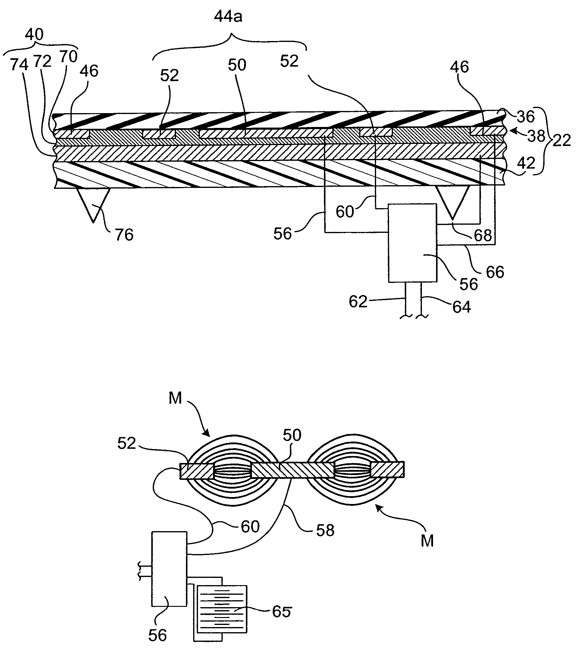
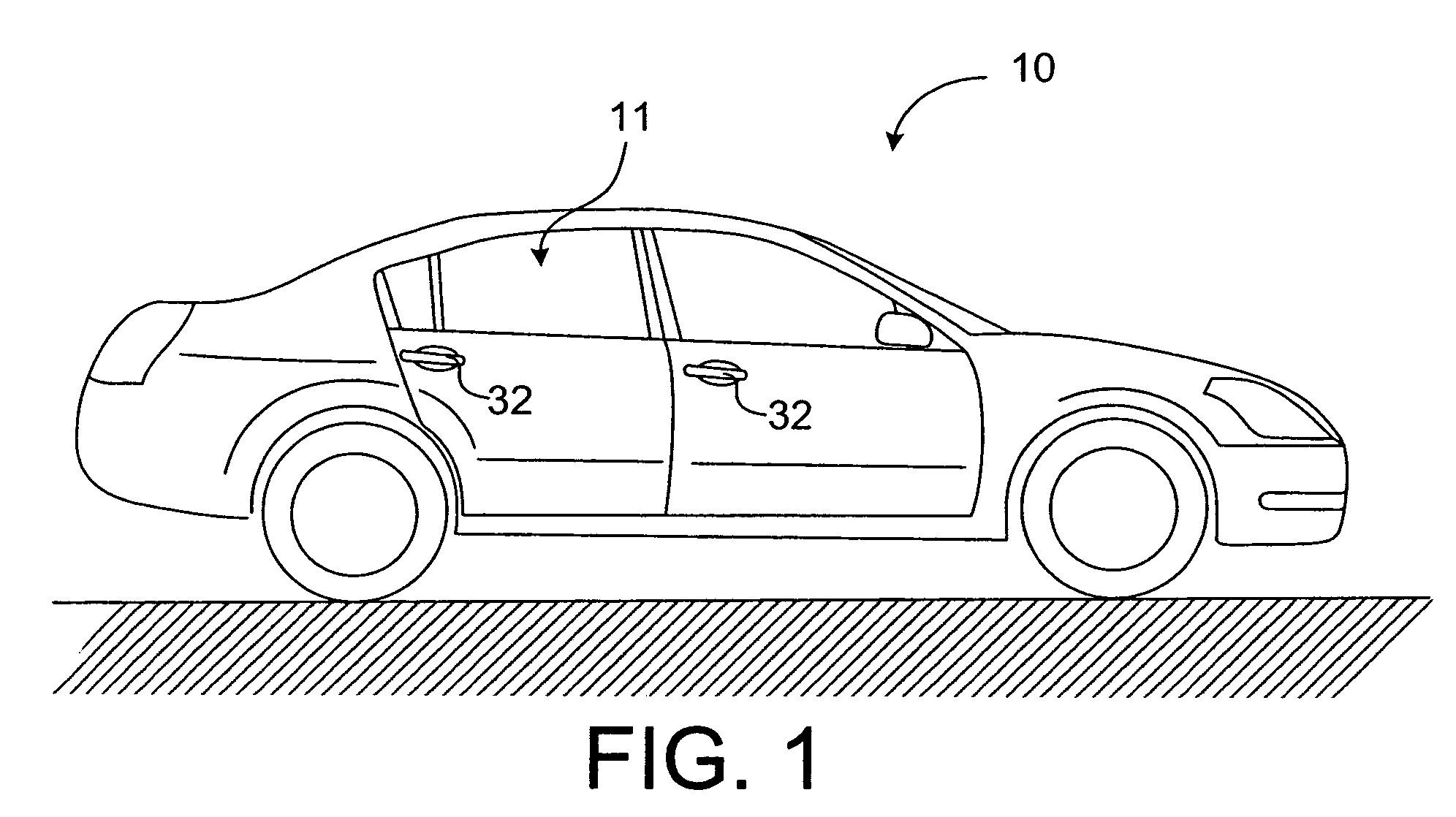
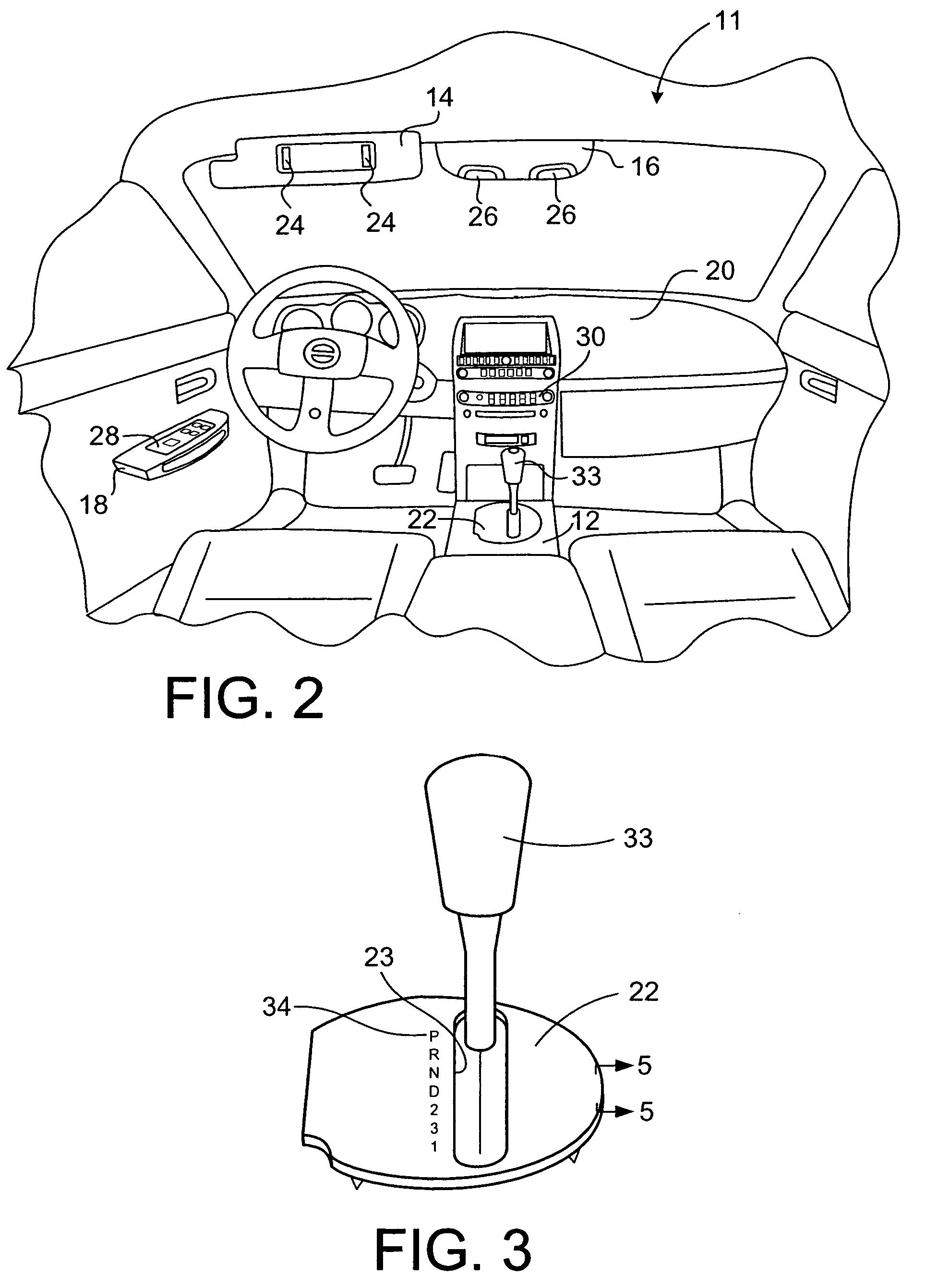
[0034]In accordance with a first embodiment of the present invention, a description of the shifter light panel 22 is now provided with specific reference to FIGS. 3, 4 and 5. The shifter light panel 22 is, for example, a transmission shifter lever cover, bezel or trim piece that at least partially forms a portion of the center console 12 in the passenger compartment 11 of the vehicle 10. The shifter light panel 22 is formed with an aperture 23 through which a transmission shifter lever 33 extends. The shifter light panel 22 includes indicia 34 adjacent to the aperture 23 that marks locations for positions of the shifter lever 33. The indicia 34 are also herein referred to as visible graphics.

[0035]The shifter light panel 22 is a multilayered unit that includes a series of layers, which each layer formed with an aperture corresponding to the aperture 23 as shown in FIG. 4. The layers of the shifter light panel 22 form both a lighting source and a switch for turning the lighting sourc...

second embodiment

[0062]Referring now to FIG. 10, the switch light panel 28 in accordance with a second embodiment will now be explained. In view of the similarity between the first and second embodiments, the parts of the second embodiment that are identical to the parts of the first embodiment will be given the same reference numerals as the parts of the first embodiment. Moreover, the descriptions of the parts of the second embodiment that are identical to the parts of the first embodiment may be omitted for the sake of brevity. The parts of the second embodiment that differ from the parts of the first embodiment will be indicated with a single prime (′) or a new reference numeral.

[0063]The switch light panel 28 is, for example, a window control panel that controls the operation of driver and passenger side windows. The switch light panel 28 includes seven separate areas of indicia 134a through 134g (visible graphics). Indicia 134a and 134b are headings that identify driver and passenger switch ar...

third embodiment

[0077]Referring now to FIG. 14, a flowchart is shown demonstrating operation of the switch light panel 28 in accordance with a third embodiment of the present invention will now be explained. In view of the similarity between the second and third embodiments, the parts of the third embodiment that are identical to the parts of the second embodiment will be given the same reference numerals as the parts of the second embodiment. Moreover, the descriptions of the parts of the third embodiment that are identical to the parts of the second embodiment may be omitted for the sake of brevity.

[0078]In the third embodiment, the controller 156 of the second embodiment can be configured to operate in a manner slightly different that shown in FIG. 13.

[0079]Specifically, as shown in FIG. 14, the controller 156 of the third embodiment is programmed to turn on the electroluminescent element 40′ in response to input from any one of the proximity switches 144a through 144e.

[0080]For instance, as in...


PUM


Abstract

A light panel includes an outer layer, a first proximity switch, an electroluminescent element and a base portion. The outer layer includes a translucent portion. The first proximity switch is disposed beneath the outer layer and has first and second electrically conductive switch portions that are arranged to form an electric field that emanates through the outer layer when the first proximity switch is energized. The electroluminescent element is disposed beneath the outer layer to provided backlighting to the outer layer. One of the first and second electrically conductive switch portions of the first proximity switch forms at least a portion of an electrode of the electroluminescent element. The base portion is disposed beneath the electroluminescent element and the first proximity switch.

Description

BACKGROUND OF THE INVENTION[0001]1. Field of the Invention[0002]The present invention generally relates to a light panel with an integrated switch. More specifically, the present invention relates to a light panel having a proximity switch and an electroluminescent element where an electrode of the electroluminescent element is at least partially defined by an electrically conductive portion of the proximity switch.[0003]2. Background Information[0004]A proximity switch is a device that includes a structure that generates a magnetic field and circuitry that detects the proximity of an object (such as a finger) that disturbs the electric field when close to or in contact with the surface of the proximity switch. Proximity switches are gradually being integrated into a variety of technologies, including the automotive industry for use in interior switch applications. One of the advantages of proximity switches is that they require very little space compared to mechanical switch techno...

Claims


Application Information

Patent Timeline
Patent Type & Authority Patents(United States)
IPC IPC(8): F21V9/16
CPCB60Q3/0283B60Q3/0296H03K17/962H03K17/96H03K2217/960785B60Q3/745B60Q3/82
Inventor KONET, HEATHER S.GRAY, JASON M.MILLER, MICHAEL R.STERLING, JENNIFER J.
Owner NISSAN MOTOR CO LTD
Why Eureka
Try Eureka