Method for identifying tooth-colored tooth filling residues

a technology of tooth filling and residue, which is applied in the field of method and apparatus for identifying tooth filling residue, can solve the problems of difficult to distinguish healthy teeth from healthy teeth, complicated apparatus, and difficulty in seeing whether the filling has been completely removed, and achieves the effects of fewer fluctuations, convenient for dentists, and easy detection of tooth filling residues

Active Publication Date: 2008-11-04
CARL ZEISS SMT GMBH
View PDF14 Cites 6 Cited by
  • Summary
  • Abstract
  • Description
  • Claims
  • Application Information

AI Technical Summary

Benefits of technology

[0026]In the apparatus according to the invention the light with which the irradiation operation is effected can involve, in at least one direction, a profile with a constant intensity distribution. If the irradiation device is so designed that it illuminates the tooth in point form, the point can have in particular an intensity distribution which has a constant portion in the radial direction. As stated above, a profile with an intensity distribution which has a constant portion, for example a hat top profile, can have the advantage over a Gaussian profile that fewer fluctuations in intensity occur in the irradiated region of the tooth.
[0027]In addition the irradiation device of the apparatus according to the invention can be integrated into an operating microscope or an OP-illumination means. It will be appreciated that it can also be in the form of an independent unit. Furthermore the apparatus according to the invention can include a scanning unit for scanning the tooth. Finally it may also have an adjusting device for adjusting the level of intensity of the light used for the irradiation procedure in order to give the user the option of adjusting an intensity which makes it easier for him to detect the tooth filling residues and which is pleasant for him.

Problems solved by technology

For some time now tooth fillings have been used in dental medicine, which can no longer be readily distinguished from healthy tooth.
If those fillings have to be removed it is difficult for the dentist to see whether the filling has been completely removed.
However such an apparatus requires relatively complicated and expensive analysis of the scattered light as well as a relatively high level of technical expenditure for displaying the result of the analysis procedure.

Method used


Image

  • Method for identifying tooth-colored tooth filling residues
  • Method for identifying tooth-colored tooth filling residues
  • Method for identifying tooth-colored tooth filling residues

Examples


first embodiment

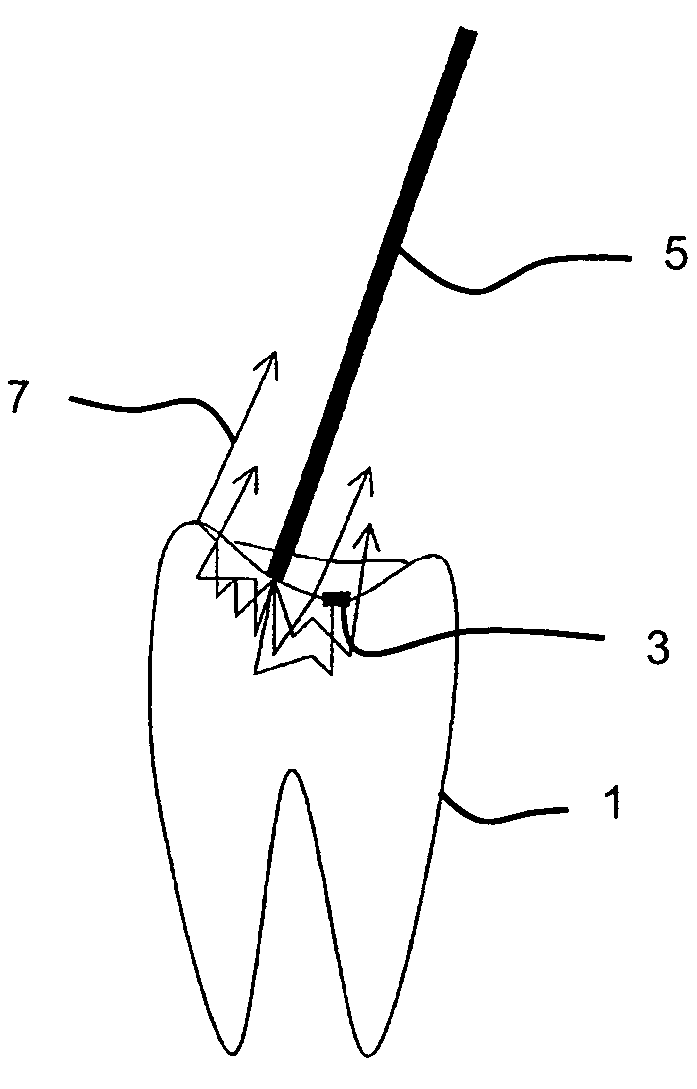
[0038]the method according to the invention is described hereinafter with reference to FIG. 1.

[0039]Referring to FIG. 1 illustrated therein are a tooth 1, a tooth filling residue 3 and a light beam 5 with which the tooth 1 is irradiated in a locally limited region. In the radial direction the light beam 5 involves the hat top profile illustrated in FIG. 8 as its intensity profile and is preferably formed from coloured and in particular monochromatic light. The wavelength or wavelengths of the light beam 5 is or are so selected that the light is strongly scattered by the tooth material, in particular the dentine, but is greatly absorbed by the tooth filling material. In the present embodiment red or green light is used. The light scattered by the tooth material then issues inter alia around the irradiated region, as is indicated by the arrows 7 in FIG. 1. Therefore a coloured halo appears around the illumination point. The scattered light is however absorbed by the tooth filling mate...

second embodiment

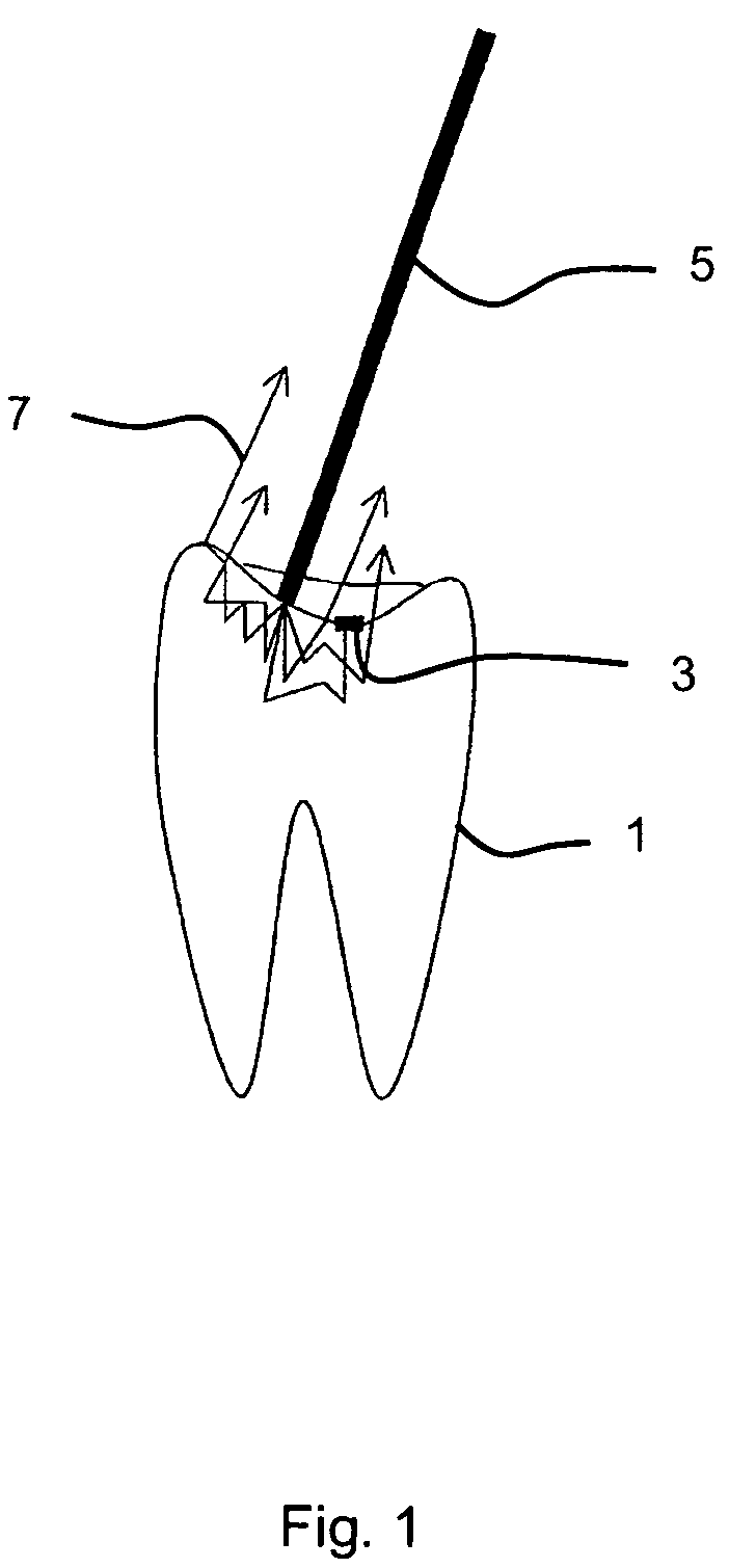
[0042]FIG. 2 shows the method according to the invention. In this embodiment the tooth is irradiated with light 5′ over a large area. The light used for the irradiation procedure involves a spectrum with irregularly distributed wavelengths and is preferably of an intensity which is substantially constant over the entire irradiation cross-section. It appears white however in the blend of the wavelengths. In the illustrated embodiment the spectrum includes red, green and blue light, as is indicated in FIG. 2 by dotted, solid and broken lines respectively. The light 5′ is scattered by the tooth material and a part of the scattered light 7 issues from the tooth 1 again. As the tooth material, in particular the dentine, scatters visible light only with a very low level of wavelength dependency, the scattered light 7 appears substantially white like the light 5′ with which the tooth 1 is irradiated.

[0043]In contrast to the tooth material however the tooth filling material involves wavelen...

fifth embodiment

[0060]the apparatus according to the invention is shown in FIG. 7. The apparatus 50 includes a light source 52 and an optical irradiation means 51, by means of which the tooth can be irradiated with the light from the light source in particular over a large area and uniformly. It is also advantageous in this embodiment if the beam cross-section involves a constant intensity distribution.

[0061]The light source 52 is of such a nature that its colour temperature can be varied by means of an adjusting device 53 connected to the light source. For the purposes of identifying tooth filling residues, the colour temperature can be varied by means of the adjusting device until a colour temperature is set, at which the tooth filling material differs from the tooth material. If the scattering or absorption characteristics of the tooth filling material are known, the colour temperature can also be already set prior to the irradiation procedure, in such a way that the tooth filling material can b...


PUM

PropertyMeasurementUnit
wavelengthsaaaaaaaaaa
brightnessaaaaaaaaaa
temperatureaaaaaaaaaa

Abstract

A tooth is irradiated with light (5), in particular with visible light for identifying tooth-colored tooth filling residues (3) of the tooth. The light with which the irradiation procedure is effected includes at least one wavelength component that is absorbed or scattered by the tooth filling material differently from the tooth material in such a way that the tooth filling material differs from the tooth material in respect of its brightness or in respect of its color. Thus the identification of tooth filling residues (3) can be effected in such a way that the dentist can recognise the tooth filling residues (3) with the naked eye, or possibly with the assistance of simple technical aids such as for example a color filter.

Description

BACKGROUND OF THE INVENTION[0001]1. Field of the Invention[0002]The invention concerns a method and apparatus for identifying tooth-coloured tooth filling residues.[0003]2. Description of the Related Art[0004]For some time now tooth fillings have been used in dental medicine, which can no longer be readily distinguished from healthy tooth. If those fillings have to be removed it is difficult for the dentist to see whether the filling has been completely removed.[0005]Therefore technical aids have been proposed for discovering tooth filling residues. DE 196 19 067 proposes distinguishing tooth filling residues from the tooth-substance on the basis of the differing scatter characteristics thereof in relation to Raman scattering. To find tooth filling residues, the free end of an optical fibre, at the other end of which there is a laser, is directed on to the tooth. Light scattered by the tooth substance is collected by means of a collector device and fed to an evaluation unit where it...

Claims


Application Information

Patent Timeline
Patent Type & Authority Patents(United States)
IPC IPC(8): A61C5/00A61C1/00A61B5/00A61C13/08G01N21/88
CPCA61C13/082G01N21/8803A61B5/0088G01N21/8806G01N2021/8845
Inventor HAISCH, MICHAELMONZ, LUDWIN
Owner CARL ZEISS SMT GMBH
Why Eureka
Try Eureka