
Machine for finishing an object such as a profiled element, a panel, or suchlike

a technology for profiling elements and finishing machines, which is applied in the direction of grinding machines, maintenance and safety accessories, coatings, etc., can solve the problems of difficult to guarantee the safety of workers, and difficult to achieve the effect of simple and complex finishing machines

Inactive Publication Date: 2008-11-04
DELLE VEDOVE LEVIGATRICI
View PDF17 Cites 0 Cited by
  • Summary
  • Abstract
  • Description
  • Claims
  • Application Information

AI Technical Summary

Benefits of technology

The modular design enhances safety by preventing operator access and waste material escape, reduces production and maintenance costs, and allows for flexible operation without specific design changes for different finishing operations.

Problems solved by technology

This alternated arrangement of the supporting frames however, entails a lateral bulk that is irregular with respect to the base, causing problems of safety, in order to limit the risk of accidents.
It is therefore difficult to guarantee the safety of the workers, especially to prevent them from accessing the zone where the abrasive belt, or abrasive grinding wheel, contacts the object, and to prevent the accidental escape from said zone of chip or other waste materials.
It is also difficult to guarantee the safety of the workers, to prevent their access to the zone where the objects pass from one work station to another, guided by profiles with guide wheels and pressed on the feed means by other pressure wheels.
On the one hand, this choice allows wide flexibility in setting up the machine, but on the other hand it entails, on each occasion, a specific design of the base according to the type of work stations that have to be mounted, with a consequent increase in production times and costs, and also in the management of the spare parts in store.
Another disadvantage is that, on each occasion, specific connection members have to be provided, which allow the various feed means to be mounted on the base.

Method used


Image

  • Machine for finishing an object such as a profiled element, a panel, or suchlike
  • Machine for finishing an object such as a profiled element, a panel, or suchlike
  • Machine for finishing an object such as a profiled element, a panel, or suchlike

Examples


Embodiment Construction

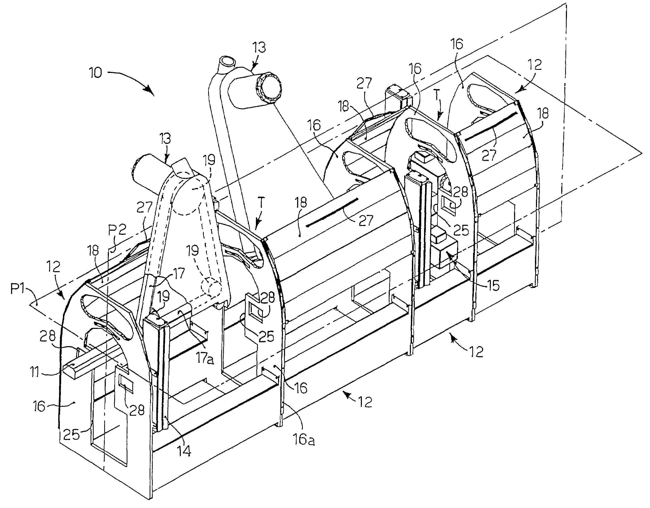
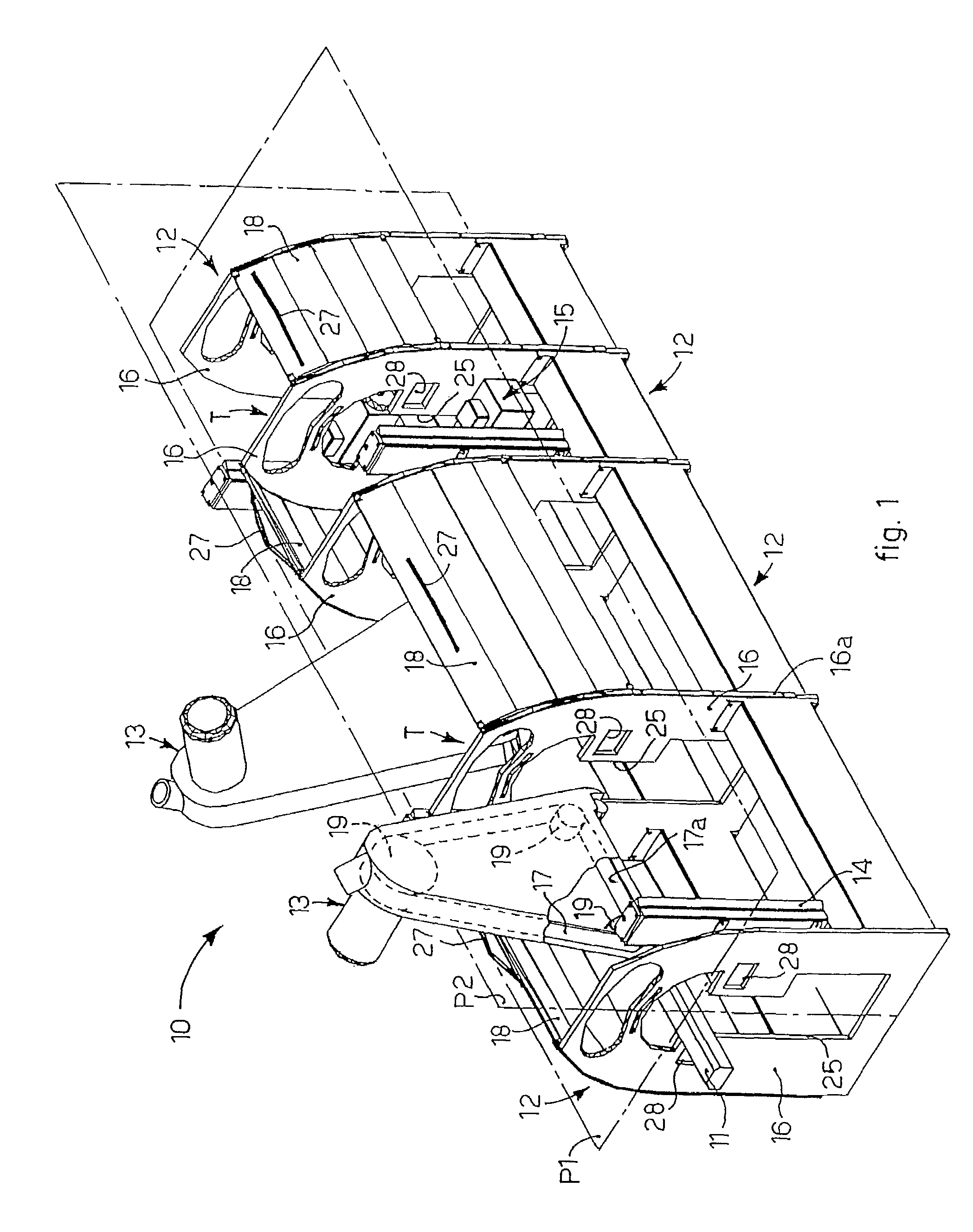
[0039]With reference to FIG. 1, a machine 10 for finishing an object 11 according to the present invention in this case consists substantially of four modules 12 arranged in line, each one comprising a specific work station.

[0040]In this case, the first two modules 12 comprise respective work stations provided with belt-type smoothing machines 13, while the last two modules 12 comprise work stations provided with further finishing members 15, not shown in detail and of a substantially known type, such as for example smoothing members with grinding wheels, painting members, cutting members, covering members or other.

[0041]For simplicity of description, the object 11 finished by the machine 10 according to the invention will be indicated hereafter as a profiled element 11, but this does not excludes that the object may be for example a lath of a frame, a panel or suchlike, made of any material whatsoever, like wood, metal, plastic or other.

[0042]The machine 10 according to the inventi...


PUM


Abstract

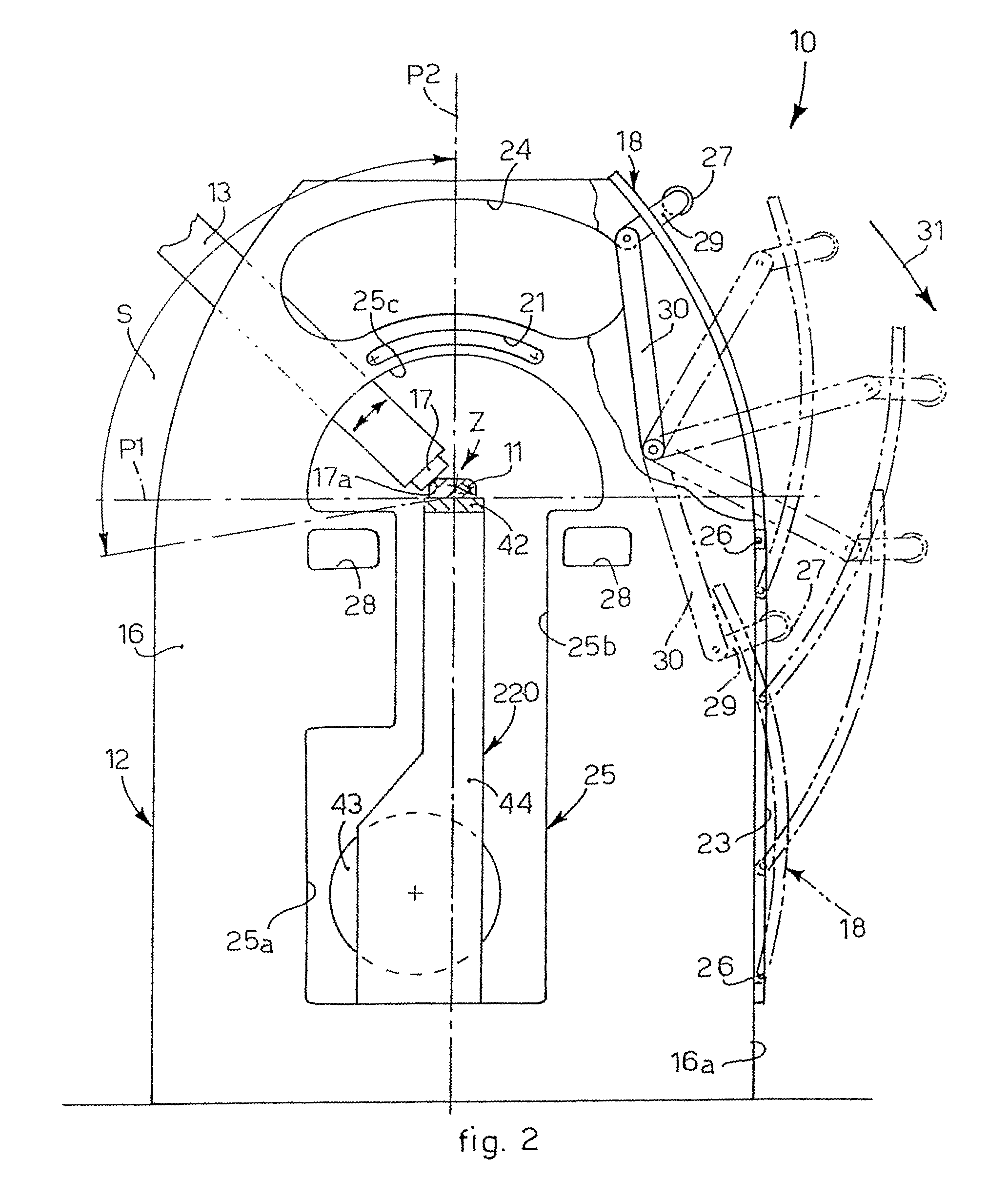
A machine for finishing an object comprising feed members to feed the object along a reference plane (P1), and at least a work station provided with a tool which contacts the object in a work zone (Z) near the reference plane (P1). The machine comprises two lateral supporting walls arranged substantially orthogonal both to the reference plane (P1) and also to the median plane (P2), which support the work station laterally, in order to define with the work station a modular structure able to be selectively associated with other modular structures along the direction of feed of the object.

Description

FIELD OF THE INVENTION[0001]The present invention concerns a machine for finishing an object such as a profiled element, a panel, or suchlike, made of any material such as wood, metal, plastic or other. To be more exact, the machine according to the invention comprises a plurality of work stations arranged in line, which can be, for example, for smoothing, painting, cutting, covering or other operations.BACKGROUND OF THE INVENTION[0002]A machine is known for finishing an object, such as a wooden profiled element, or suchlike, which comprises feed means to feed the object to be finished along a reference plane.[0003]The machine also comprises one or more work stations mounted in line on the base, along the reference plane, at a determinate distance from each other, in order to finish longitudinally the outer surfaces of the object.[0004]Generally, part of the work stations is able to smooth the outer surfaces of the object, and comprises a supporting frame, or operative assembly, ins...

Claims


Application Information

Patent Timeline
Patent Type & Authority Patents(United States)
IPC IPC(8): B24B7/00B24B9/00B05B13/02B05C9/10B23Q7/14B23Q11/08B24B7/06B24B7/28B24B21/04B24B55/04B27C1/02
CPCB24B7/06B24B7/28B24B21/04B24B55/04
Inventor DELLE VEDOVE, GAETANO
Owner DELLE VEDOVE LEVIGATRICI
Learn More