Imprinting nanoscale patterns for catalysis and fuel cells

a fuel cell and nano-scale technology, applied in secondary cell manufacturing, electrode manufacturing processes, final product manufacturing, etc., can solve the problems of not providing the required nano-scale resolution, e-beam lithography is too expensive and slow, and the nano-scale pattern would exceed the lower limit of optical lithography, etc., to improve catalysis and fuel cell efficiency, efficient and better energy conversion

Active Publication Date: 2008-11-04
SAMSUNG ELECTRONICS CO LTD
View PDF12 Cites 45 Cited by
  • Summary
  • Abstract
  • Description
  • Claims
  • Application Information

AI Technical Summary

Benefits of technology

[0002]This invention provides a means for making designed nanoscale catalyst patterns using a nanoimprinting process to improve catalysis and fuel cell efficiency. In addition, the invention includes an embodiment which enables the fuel molecule, appropriate catalytic surface, conductor, and ionic transport layer of a fuel cell to all meet in a more efficient and structured manner for better energy conversion than existing systems.

Problems solved by technology

However, nanoscale patterns would exceed the lower limits of optical lithography.
Similarly, e-beam lithography is too expensive and slow, and in many cases, can not provide the required nanoscale resolution.
However, this technique does not enable the separation of oxidation and reduction reaction processes in a method permitting easy redirection of electron transfer toward their utilization as an electric power source.

Method used


Image

  • Imprinting nanoscale patterns for catalysis and fuel cells
  • Imprinting nanoscale patterns for catalysis and fuel cells
  • Imprinting nanoscale patterns for catalysis and fuel cells

Examples


Embodiment Construction

I. Preparing the Mold

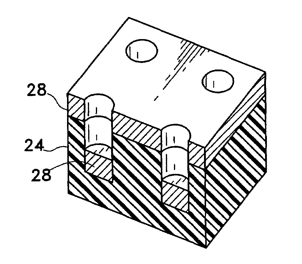
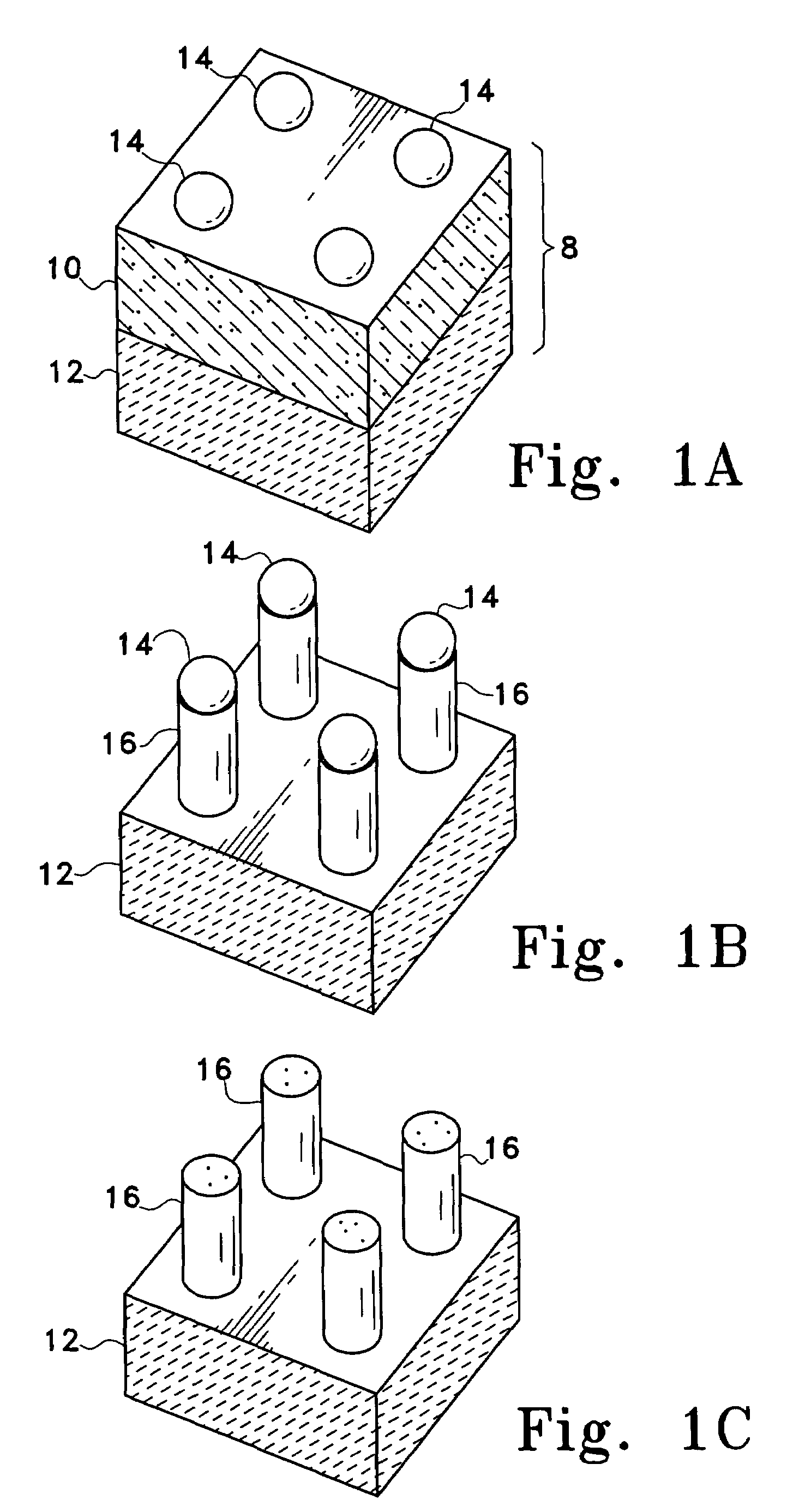
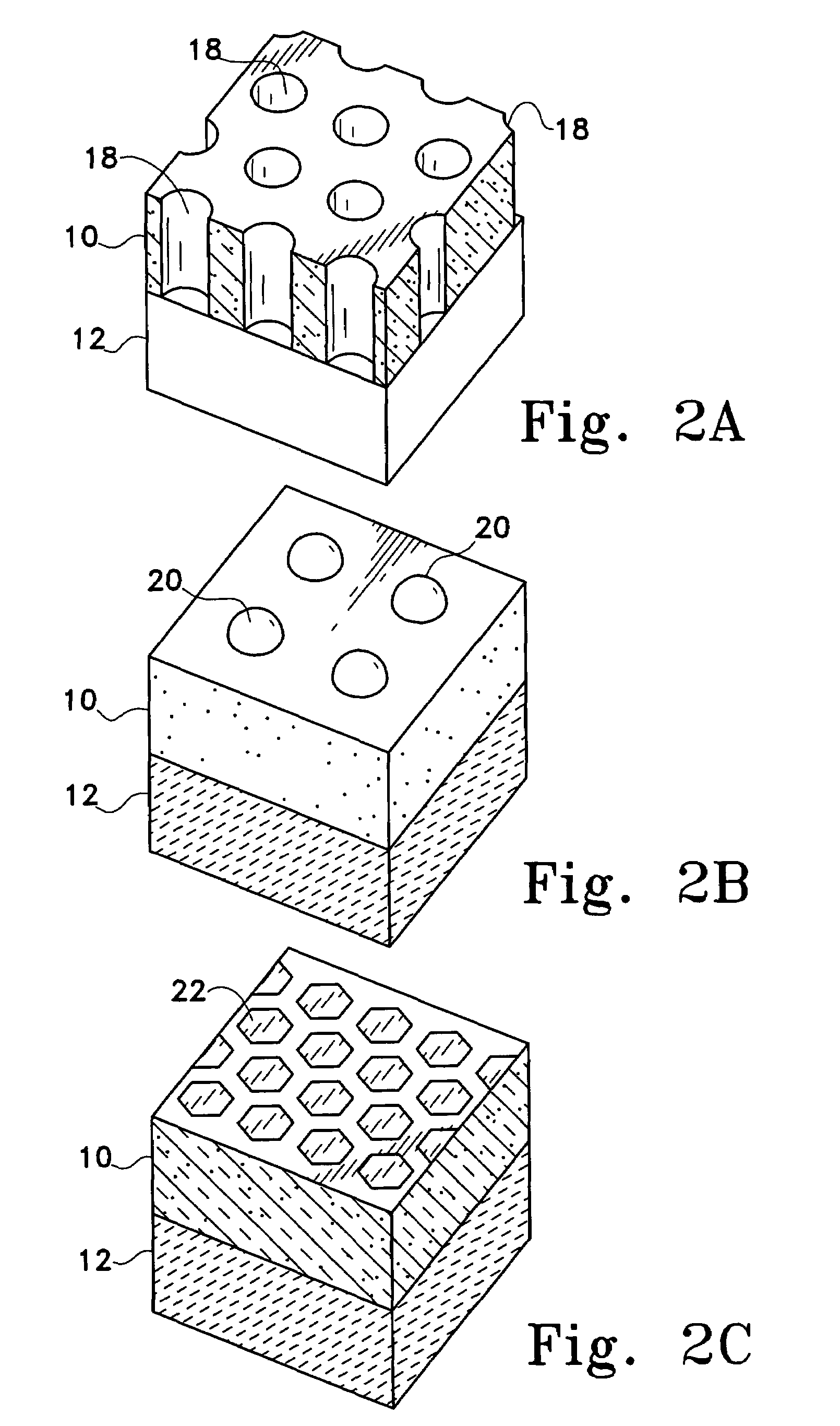
[0015]The present invention includes methods for making a mold, which has at least one protruding feature having nanoscale dimensions, and using the mold to imprint a membrane, thereby creating a recessed feature, which is a reverse copy of the protruding feature, in the membrane.

[0016]In general, the body of the mold should be constructed of materials that are hard relative to the membrane used during the imprinting process. For example, the mold can be made of metals, dielectrics, semiconductors, ceramics, polymers or combinations thereof. Typically, the mold will include a plurality of features having a desired shape. In a preferred embodiment, the mold is silicon or silicon dioxide.

[0017]The mold is patterned with protruding and / or recessed features, such as pillars, holes, dams, and trenches, with a minimum lateral feature size of about 1 nm. The typical depth (or height) of a feature is from 1 nm to 100 μm, depending on the desired lateral dimension. In ce...


PUM

PropertyMeasurementUnit
heightaaaaaaaaaa
depthaaaaaaaaaa
diameteraaaaaaaaaa

Abstract

A method and mold for creating nanoscale patterns in an ion-selective polymer membrane is provided, in which a mold comprising a substrate and a molding layer having at least one protruding feature is imprinted on the ion-selective polymer membrane, thereby creating a recessed feature in the membrane. Protruding features having nanoscale dimensions can be created, e.g., by using self-assembled nanostructures as a shadow mask for etching a molding layer. In one embodiment, an imprinted ion selective polymer membrane, suitable for use as a solid electrolyte, is adapted for use in an electrochemical device or fuel cell by adding a metal catalyst to one portion of the membrane to serve as a catalytic electrode.

Description

BACKGROUND[0001]In catalytic processes, it is important to control the size and spacing of catalysts to enhance their efficiency. For the catalytic processes of fuel cells, it is even more crucial since the spacing between the catalysts will provide a channel for ions to diffuse from one electrode to another. Conventional methods, such as optical and e-beam lithography methods, have been used to make patterned catalysts to enhance catalysis efficiency. However, nanoscale patterns would exceed the lower limits of optical lithography. Similarly, e-beam lithography is too expensive and slow, and in many cases, can not provide the required nanoscale resolution. A third solution is the application of catalytic materials to a particle, often of spherical or semi-spherical shape and subsequently taking these particles and placing them in a supporting binder. An example of such a system is the catalytic “converter” used in automobile exhaust systems. However, this technique does not enable ...

Claims


Application Information

Patent Timeline
Patent Type & Authority Patents(United States)
IPC IPC(8): B29C59/00B28B3/00B29C43/04B29C33/42C25B9/23H01B1/12H01M4/04H01M4/36H01M4/38H01M4/60H01M4/86H01M4/88H01M10/04
CPCB29C33/42B82Y30/00C25B9/10H01B1/122H01M4/366H01M4/602H01M4/8807H01M4/8817H01M4/9041Y10S977/887H01M4/38H01M4/8657H01M8/1286H01M10/0472H01M2300/0082Y02E60/50Y10S977/89B29L2031/756Y02E60/10C25B9/23Y02P70/50
Inventor CHEN, YONGHACKLERNAN, DAVIDMITTELSTADT, LAURIE S.JEON, YOOCHAMWILLIAMS, RICHARD STANLEY
Owner SAMSUNG ELECTRONICS CO LTD
Why Eureka
Try Eureka