Cyclotron

a cyclotron and accelerator technology, applied in the field of cyclotrons, can solve the problems of limiting the productivity of the radioisotope production system, the risk of damage, and the capacity of the target to dissipate, and achieve the effect of easy and effective adjustmen

Inactive Publication Date: 2008-11-04
ION BEAM APPL
View PDF6 Cites 147 Cited by
  • Summary
  • Abstract
  • Description
  • Claims
  • Application Information

AI Technical Summary

Benefits of technology

[0001]The present invention relates to a cyclotron and a method that allows the position of a beam of charged particles to be easily and effectively adjusted.

Problems solved by technology

An element limiting the productivity of the radioisotope production system is the capacity of the target to dissipate the thermal capacity that the target receives by the beam.
If said target receives an intensity that is too strong from the beam (or current), it risks being damaged.
Therefore, one may not fully utilize the production capacities of the cyclotron in this scenario, essentially due to the fact that one cannot manage to sufficiently cool the target.
Nevertheless, owing to, for example, a defect in the symmetry of the cyclotron, it could be that one of the targets receives a beam intensity that is essentially different from that received by the other target.
Then it may happen that one of the targets could be damaged by a current that is too strong.
However, this solution is delicate and costly, since it requires the installation of adjustable mobile equipment within the same machine, that is, in the vacuum chamber.
This solution thus allows the intensity of the beams to be adjusted, but presents the following disadvantages: in particular, the harmonic coils must be located at the hills, where the gap is the narrowest.
Thus, the coils may be directly reached by the beam, more particularly in the case of a defect in the axial alignment of said beam, which will inevitably lead to the destruction of said coils.
Furthermore, as these coils are disposed in the vacuum chamber, the conductors powering these coils must traverse the wall of said chamber by means that respect a complete leakproofness, which may pose difficulties.
However, cases where these two curves never intersect have been observed following thermal drift, or due to dissymmetries in the construction of the cyclotron.
It is then impossible to equalize the currents hitting the two targets by this method.

Method used


Image

  • Cyclotron
  • Cyclotron
  • Cyclotron

Examples


Embodiment Construction

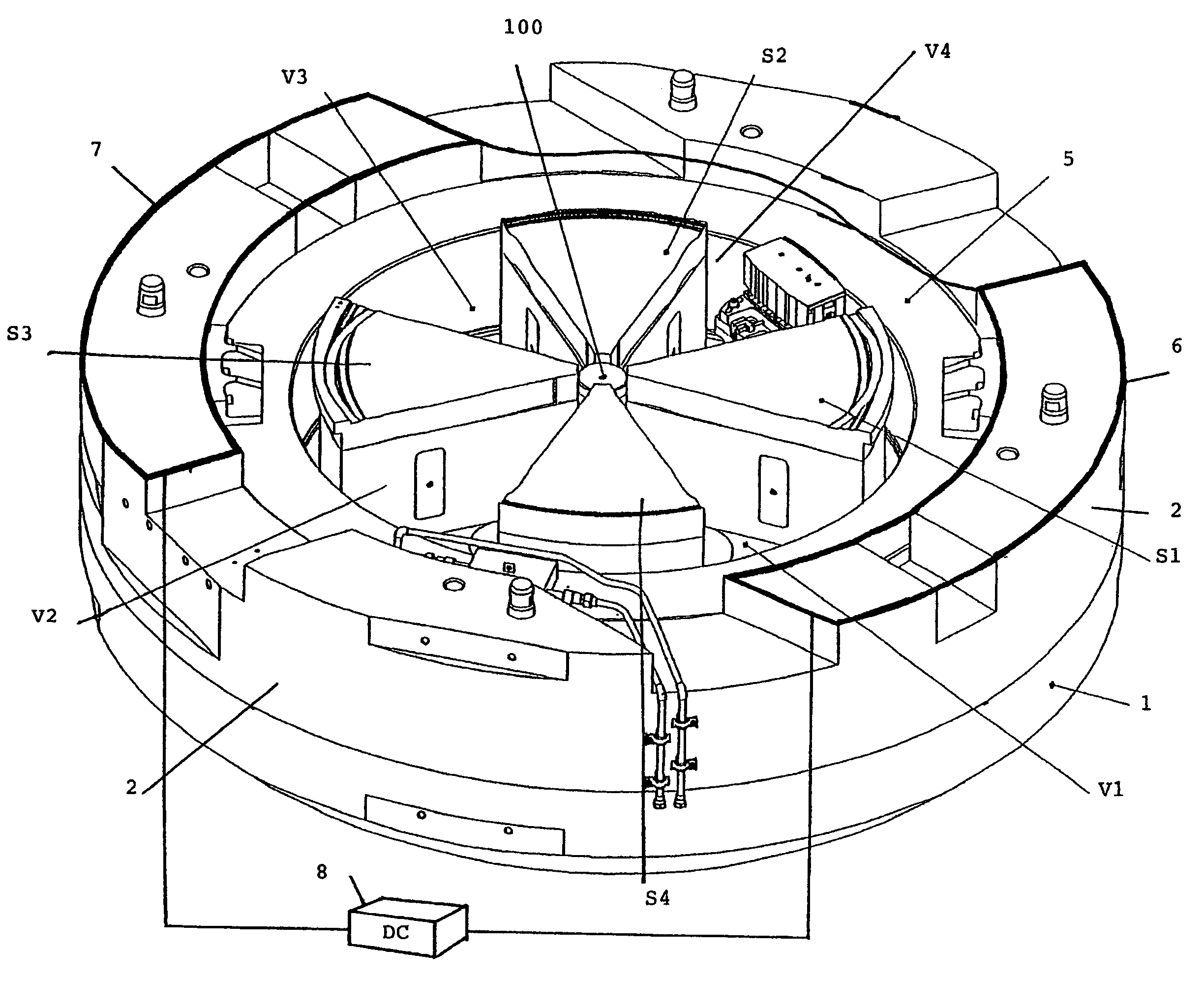
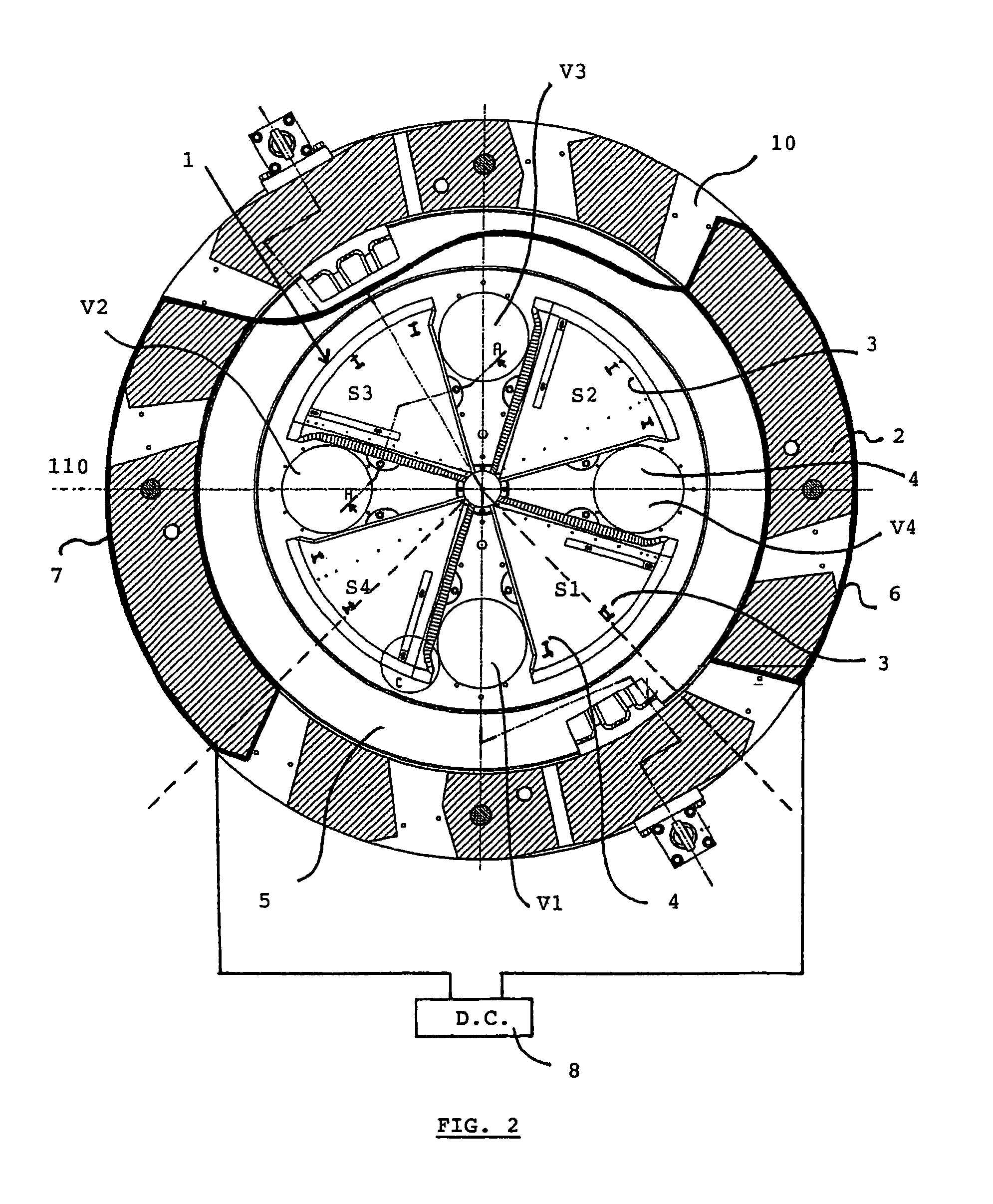
[0042]FIGS. 2, 3 and 4 show a compact isochronous cyclotron utilized in the framework of a preferred embodiment of the present invention. This cyclotron conventionally comprises several subsystems:[0043]a. a magnetic circuit,[0044]b. an RF acceleration device,[0045]c. a vacuum chamber[0046]d. charged particle injection means,[0047]e. accelerated charged particle extraction means.

[0048]The magnetic circuit is essentially comprised of an electromagnet presented in the form of two poles, an upper pole 1 (not represented in FIGS. 2 and 3) and a lower pole 1′, symmetrically disposed with relation to a median plane 110 perpendicular to the central axis 100 of the cyclotron. These poles 1, 1′ essentially have a cylindrical form and are separated by a gap 120.

[0049]In addition, the magnetic circuit is completed by flux returns 2 that close the circuit.

[0050]According to the particular embodiment represented in the figures, the two upper 1 and lower 1′ poles of the electromagnet each compris...


PUM


Abstract

The invention relates to a cyclotron which can produce a beam of accelerated charged particles that are intended for the irradiation of at least one target (200). The inventive cyclotron consists of a magnetic circuit which essentially comprises: an electromagnet with at least two poles (1, 1′), namely an upper pole (1) and a lower pole (1′), which are disposed symmetrically in relation to a mid-plane (110) which is perpendicular to the central axis (100) of the cyclotron and which are separated by a gap (120) containing the circulating charged particles and return flux (2) in order to close the aforementioned magnetic circuit; and a pair of main induction coils (5, 5′) which are used to create an essentially-constant main induction field in the gap between poles 1 and 1′. The invention is characterised in that it comprises means of centring the above-mentioned beam, consisting of at least one pair of bucking coils (6, 7) which are supplied by an electrical source (8) and which can modulate the intensity of the main induction field produced by the main coils (5, 5′), in order to increase the intensity of the induction field in a first area of the cyclotron and to reduce the intensity of the induction field in a second area of the cyclotron, which is diametrically opposed to the central axis (100) of the cyclotron.

Description

OBJECT OF THE INVENTION[0001]The present invention relates to a cyclotron and a method that allows the position of a beam of charged particles to be easily and effectively adjusted.TECHNOLOGICAL BACKGROUND AND PRIOR ART[0002]Cyclotrons are circular accelerators allowing the acceleration of charged particles such as positive ions (protons, deuterons, helions, alpha particles, etc.) or negative ions (H″, D−, etc.), which are utilized among others for producing radioactive isotopes, for radiation therapy, or for experimental purposes.[0003]The first cyclotrons comprised a magnetic circuit that was simply comprised of two symmetrical poles disposed on both sides of a median plane and separated by a gap in which the accelerated particles circulate. The magnetic circuit is supplemented by flux returns in order to close said circuit and cylinder heads used as base plates at the poles. The poles are surrounded by a pair of induction coils supplied by a current, which generates a uniform and...

Claims


Application Information

Patent Timeline
Patent Type & Authority Patents(United States)
IPC IPC(8): H05H13/00
CPCH05H7/10H05H13/00
Inventor JONGEN, YVESGENIN, FREDERIC
Owner ION BEAM APPL
Why Eureka
Try Eureka