Mirror reflective element assembly including electronic component

a technology of electronic components and mirror assemblies, applied in the field of rearview mirror assemblies, can solve the problems of adding to the size, weight and volume requirements of mirror assemblies, costly manufacturing and assembly, and reducing the efficiency of manufacturing and assembly, so as to improve the manufacturing and assembly process, the effect of low cost and convenient manufacturing

Inactive Publication Date: 2008-11-04
DONNELLY CORP
View PDF168 Cites 241 Cited by
  • Summary
  • Abstract
  • Description
  • Claims
  • Application Information

AI Technical Summary

Benefits of technology

[0008]For example, a third surface electro-optic or electrochromic transflective element assembly may include a metallic reflective coating or layer and one or more non-metallic, semi-conductive layers disposed at or on a third surface or front surface of the rear or second reflective element substrate. The rear reflective element substrate of the electrochromic reflective element assembly is positioned rearward of the front reflective element substrate, with an electrochromic medium disposed between the front and rear reflective element substrates. The third surface transflective element assembly thus may provide a reflective surface for viewing by the driver of the vehicle through the front reflective element substrate of the reflective element assembly. Alternately, a fourth surface electro-optic or electrochromic reflective element assembly may have a reflective coating or layer disposed on a fourth or rear surface of the rear reflective element substrate for viewing by a driver of the vehicle through the front and rear reflective element substrates or glass substrates of the reflective element assembly or cell. Alternately, the rear surface of a prismatic element or substrate may have a reflective layer disposed thereon or applied thereto for viewing by the driver of the vehicle.
[0014]Therefore, the interior rearview mirror assembly of the present invention provides a mirror reflective element assembly, such as an electro-optic or electrochromic mirror reflective element assembly or cell or a prismatic reflective element assembly, that includes a conductive trace and circuitry applied to or disposed at a rear surface of a reflective element substrate, such as a rear glass substrate of an electro-optic or electrochromic reflective element assembly or a single glass substrate of a prismatic reflective element assembly or the like, such that at least one electronic component and / or circuitry is integral with the reflective element substrate of the reflective element assembly. The reflective element assembly thus provides a circuitry on glass arrangement and thus utilizes the existing rigid glass reflective element substrate of the reflective element assembly as the rigid surface that receives the conductive trace and circuitry or electronic components thereon. The electronic components and / or circuitry thus are not provided on a separate rigid printed board or substrate that may be snapped onto or otherwise attached to an attachment plate adhered to or otherwise positioned at the rear surface of the reflective element. The rearview mirror reflective element assembly of the present invention thus provides a compact reflective element assembly, which may be readily manufactured, because the reflective element assembly does not include an attachment plate or the like. The mirror reflective element assembly of the present invention thus may provide a low cost, lightweight and compact reflective element assembly that provides for enhanced manufacturing and assembly processes.

Problems solved by technology

The attachment plate and printed board / substrate include multiple parts and components at the rear of the mirror element, which may be costly to manufacture and assemble.
The multiple components also add to the size, weight and volume requirements for the circuit board, which thus may add to the size and weight of the mirror assembly.
Also, the printed board or substrate material may add to the weight and to the cost of the mirror assembly.

Method used


Image

  • Mirror reflective element assembly including electronic component
  • Mirror reflective element assembly including electronic component
  • Mirror reflective element assembly including electronic component

Examples


Embodiment Construction

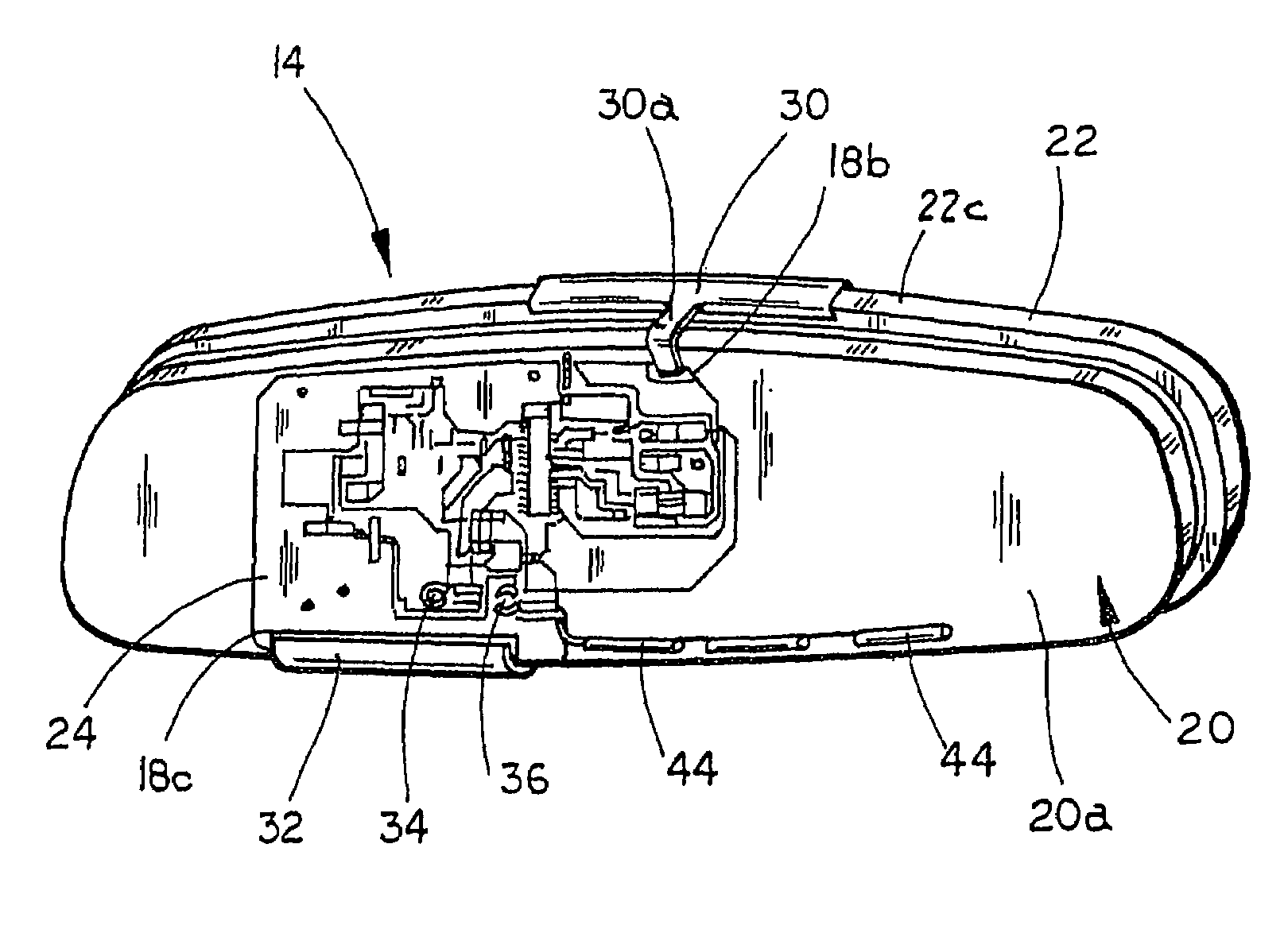
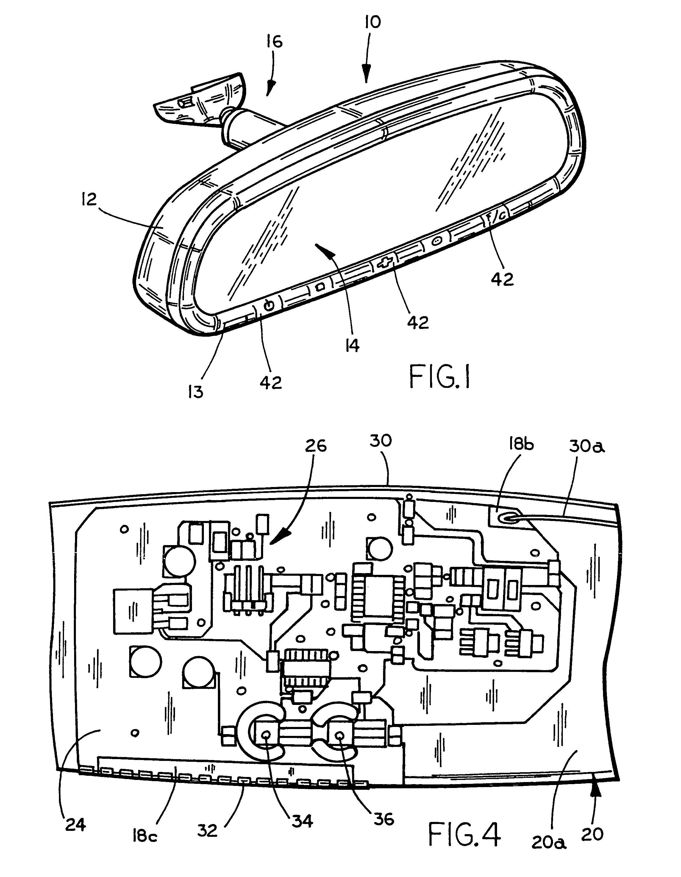
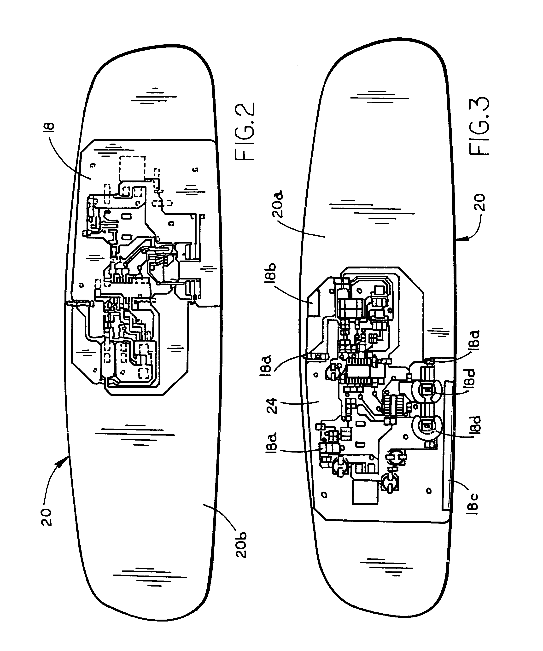
[0023]Referring now to the drawings and the illustrative embodiments depicted therein, an interior rearview mirror assembly 10 includes a casing 12, a bezel 13, a reflective element assembly or cell 14 and a mounting arrangement 16 (FIG. 1) for adjustably mounting the casing and reflective element 14 to an interior portion of a vehicle, such as to a mounting button or the like at an interior surface of a windshield of a vehicle. Mirror reflective element assembly 14 includes a conductive trace or layer or coating 18 (FIG. 2) applied to or disposed on or at the rearward surface (the surface facing forward or in the direction of travel of the vehicle when the mirror assembly is installed in the vehicle) of a reflective element substrate, such as the typically glass substrate of the reflective element assembly, such as on the rear surface 20a (FIGS. 3-6) of a second or rear substrate or glass element 20 of an electro-optic or electrochromic mirror cell (commonly referred to as the four...


PUM

PropertyMeasurementUnit
electrochromicaaaaaaaaaa
conductiveaaaaaaaaaa
transparentaaaaaaaaaa

Abstract

A reflective element assembly for a mirror assembly of a vehicle includes a reflective element substrate and a conductive trace or layer disposed at a rear surface of the reflective element substrate. A non-conductive layer is applied at the conductive layer and covers at least a portion of the conductive layer and leaves at least some portions of the conductive layer exposed. At least one circuitry component is applied to at least one of the portions of the conductive layer. The circuitry component may include a carbon ink resistor printed onto the conductive trace.

Description

CROSS REFERENCE TO RELATED APPLICATION[0001]The present application claims the benefit of U.S. provisional application Ser. No. 60 / 508,086, filed Oct. 2, 2003, which is hereby incorporated herein by reference in its entirety.FIELD OF THE INVENTION[0002]The present invention relates generally to rearview mirror assemblies for vehicles and, more particularly, to rearview mirror assemblies that include one or more electronic components, such as electro-optic or electrochromic interior rearview mirror assemblies. However, aspects of the present invention may be equally suitable for use in prismatic rearview mirror assemblies and / or for exterior rearview mirror assemblies.BACKGROUND OF THE INVENTION[0003]It is known to attach a printed circuit board to an attachment plate adhered or otherwise affixed to a rear surface of a mirror element, such as an electro-optic reflective element assembly or a prismatic reflective element. In order to attach the printed circuit board to the attachment ...

Claims


Application Information

Patent Timeline
Patent Type & Authority Patents(United States)
IPC IPC(8): G02F1/153B60R1/08
CPCB60R1/088H05K1/0274B32B37/1292H05K1/181H05K2201/2054
Inventor SCHOFIELD, KENNETHWIGHT, DAVID C.KRAMER, MARK E.
Owner DONNELLY CORP
Why Eureka
Try Eureka