
Overhead reduction in frequency hopping system for intermittent transmission

a frequency hopping system and frequency hopping technology, applied in the direction of transmission, electrical equipment, etc., can solve the problems of increasing the average power consumption of the transmitter, reducing the probability of data loss, and creating significant overhead in the transmission, so as to reduce the overhead of managing coordination, eliminate the possibility of persistent collision, and facilitate manufacturing

Inactive Publication Date: 2008-11-04
PARTYKA ANDRZEJ
View PDF9 Cites 12 Cited by
  • Summary
  • Abstract
  • Description
  • Claims
  • Application Information

AI Technical Summary

Benefits of technology

"The present invention is a wireless telemetry system that includes several remote telemetry transmitters and a telemetry collection unit. The transmitters intermittently transmit short duration messages indicative of the status of sensors associated with the transmitters. The receiver holds synchronization with the transmitters and receives the messages. The messages are transmitted at specific frequencies and time intervals. The system uses frequency hopping for wireless transmission and includes a frequency selective radio receiver circuit and a receiver control logic to process the demodulated data. The system also includes a method of transmitting to improve reliability in the presence of interference and a method of minimizing collisions. The technical effects of the invention include improved reliability, immunity against interference, and reduced battery drain."

Problems solved by technology

Second, short and infrequent transmissions lower the probability that the data is lost due to collisions that occur when two or more transmitters transmit at the same time.
In effect, a significant overhead in the transmission is created, which increases the transmitter average power consumption.
In battery operated transmitters, this overhead shortens the life of the transmitter battery thus increasing system maintenance cost and lowering system functionality and reliability.
Typically, such systems transmit data at a single frequency, and thus are susceptible to interference and signal loss due to phenomena known as “multipath fading”.
Consequently, the reliability of such systems is compromised or, conversely, the transmitted power has to be increased to overcome the fading, which results in larger power drain and shorter battery life.
Besides, there usually are regulatory limits that restrict such transmitter power and thus limit the possible compensation by sheer increase of power.
However, frequency hopping systems require a long acquisition time and they are typically used in two way communication applications in which all the devices are continuously synchronizing with one master device or with each other using a variety of synchronization methods as shown in some references.
Generally, those solutions suffer from performance degradation or high cost or both, which makes them undesirable for low cost applications that require high reliability such as security systems and many other telemetry systems.

Method used


Image

  • Overhead reduction in frequency hopping system for intermittent transmission
  • Overhead reduction in frequency hopping system for intermittent transmission
  • Overhead reduction in frequency hopping system for intermittent transmission

Examples


Embodiment Construction

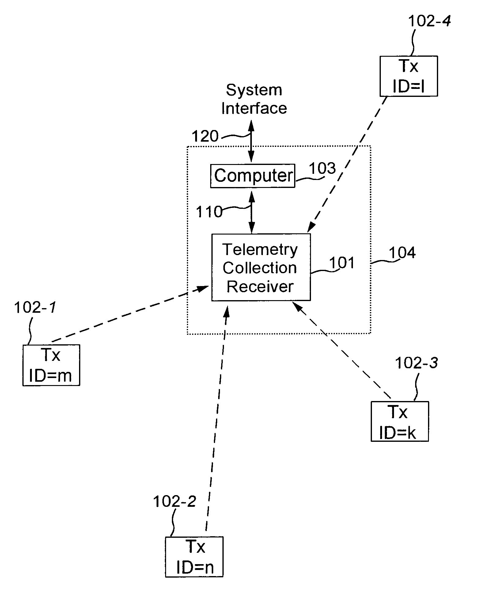
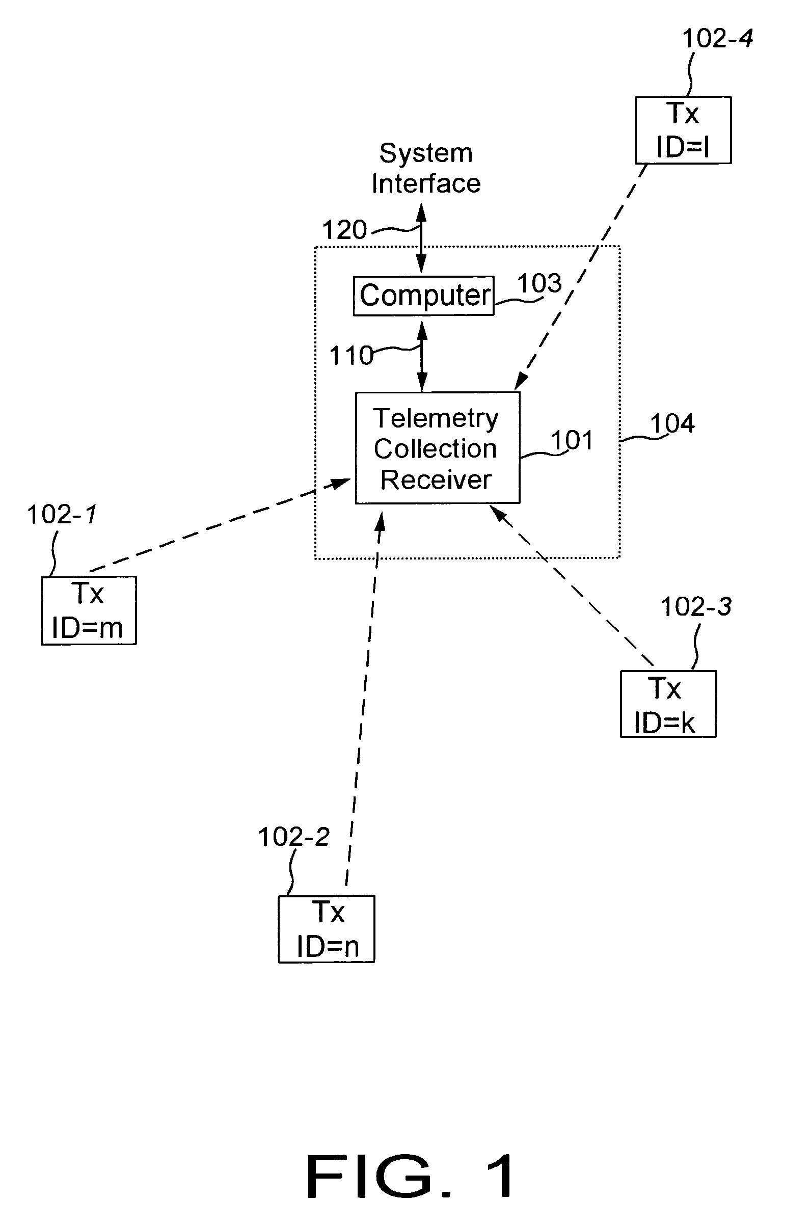
[0039]Referring to FIG. 1, the frequency hopping system includes a telemetry collection unit 104 and a plurality of remote telemetry transmitters (transmitters) 102-1, 102-2, 102-3 and 102-4. The telemetry collection unit includes a telemetry collection receiver (receiver). 101, and a computer 103 that can communicate the telemetry over system interface 120. The receiver 101 includes a system interface 110 through which the receiver can be connected, locally or remotely, to a variety of interface equipment, a controller, or a computer. Each remote telemetry transmitter includes an interface or a sensor or an operation to be monitored. Each remote telemetry transmitter intermittently transmits short messages to the telemetry collection receiver. The remote telemetry transmitters are not connected to each other and do not receive messages back from the telemetry collection receiver. The remote telemetry transmitters transmit messages when they need to without any regard to other remot...


PUM


Abstract

A radio transmission telemetry system includes several transmitters intermittently transmitting short messages indicative associated sensors status and a receiver for collecting data from the sensors. Each transmitter changes time and frequency of transmissions according to a time-frequency pattern that is different for each transmitter. The receiver identifies each source of transmissions based on its unique variations of the transmission time and frequency, thus eliminating the necessity to include the transmitter ID code in each transmitted message. Thus, overhead in the transmissions is reduced. In addition, the sensor status and other supervisory information such as battery status are partitioned and included in the transmitted messages in portions and at different rates according to the state of the PN-generator for producing the time-frequency pattern. The receiver can determine what and when is included without additional control bits in the transmitted messages. Thus, overhead in the transmissions is further reduced.

Description

CROSS-REFERENCE TO RELATED APPLICATION[0001]This application claims the benefit of, and is a continuation-in-part of U.S application Ser. No. 09 / 562,152 filed May 1, 2000, now issued U.S. Pat. No. 6,925,105, and entitled “Overhead Reduction in System for Intermittent Transmission”, which is incorporated by reference.FIELD OF THE INVENTION[0002]The present invention relates to a system in which a plurality of transmitters wirelessly transmit data for collection by one or more receivers.BACKGROUND OF THE INVENTION[0003]Some wireless telemetry systems (e.g., burglar alarms, fire alarms, power utility meters, leak detectors, environmental monitoring, plant control, etc.) comprise many transmitters that intermittently (periodically or sporadically, at constant or varying time intervals) transmit messages to one or more receivers. In these systems, the transmitters are located at different places and transmit messages that are indicative of the status of monitoring sensors to a receiver t...

Claims


Application Information

Patent Timeline
Patent Type & Authority Patents(United States)
IPC IPC(8): H04B1/00H04B1/69H04B1/713
CPCH04B1/713H04B2001/71563
Inventor PARTYKA, ANDRZEJ
Owner PARTYKA ANDRZEJ
Learn More