Disk drive storage defragmentation system

a disk drive and storage system technology, applied in the field of disk drive storage systems, can solve the problems of affecting the performance of the host computer, and difficult to locate available contiguous data blocks

Active Publication Date: 2008-11-04
SILICON VALLEY BANK +1
View PDF7 Cites 40 Cited by
  • Summary
  • Abstract
  • Description
  • Claims
  • Application Information

AI Technical Summary

Problems solved by technology

As the file system stores and updates files on the disk drive, available contiguous data blocks become difficult to locate.
This can devastate the performance of the disk drive storage system.
The fragmentation of the files on the disk drive will impact the performance of the host computer as processes await the requested file.
As the host computer repeatedly performs the above file operations over long periods of time, and as the file system starts to get full, i.e., most of the data sectors on the disk drive platters will be allocated to stored files, allocating new data blocks becomes increasingly difficult.
This requires that the disk drive actuator move to read data sectors from different locations on the disk drive platter, resulting in random seek latencies.
The problem of a single data file being stored in scattered locations is called file system fragmentation.
A fragmented file system causes an excessive amount of random seeks to access file space allocated for write and read.
This poses a substantial challenge to the disk drive technology.
With fragmented file systems, a substantial amount of random seeking and latencies may be introduced due to file fragmentation.
This can significantly reduce the data throughput, often to a level below what is required to support real-time applications such as high-definition video and digital film production.
This goal can not be achieved without taking up additional host computer resources.
However, the defragmentation process requires extra processing and data transfers.
Sometimes, if the disk drive device is almost full with user data blocks, there may not be enough available free data blocks to hold the defragmented files.
As a result, the overall data access throughput is further reduced due to the defragmentation process, defeating the original purpose which is to improve the storage system performance.
Solutions to these problems have been long sought but prior developments have not taught or suggested any solutions and, thus, solutions to these problems have long eluded those skilled in the art.

Method used


Image

  • Disk drive storage defragmentation system
  • Disk drive storage defragmentation system
  • Disk drive storage defragmentation system

Examples


Embodiment Construction

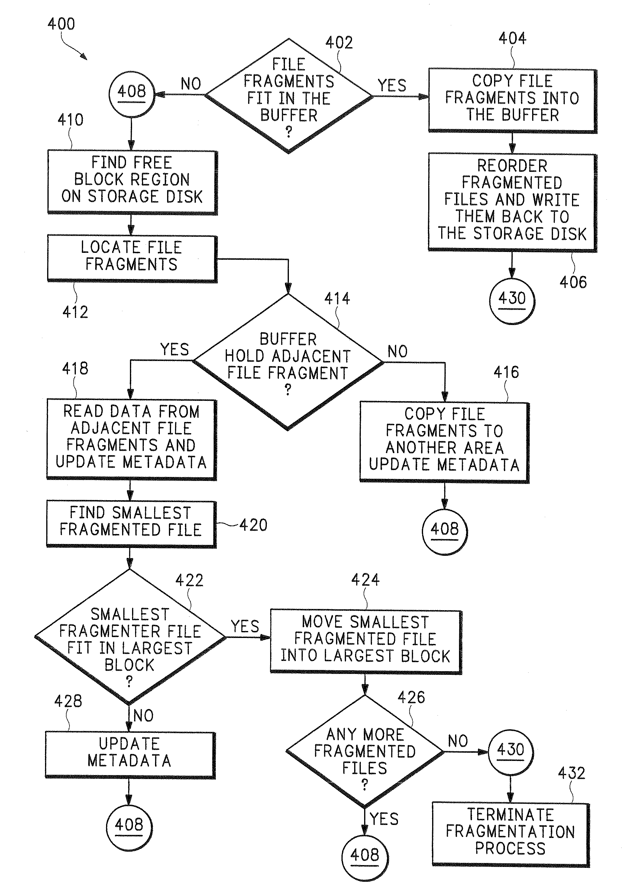
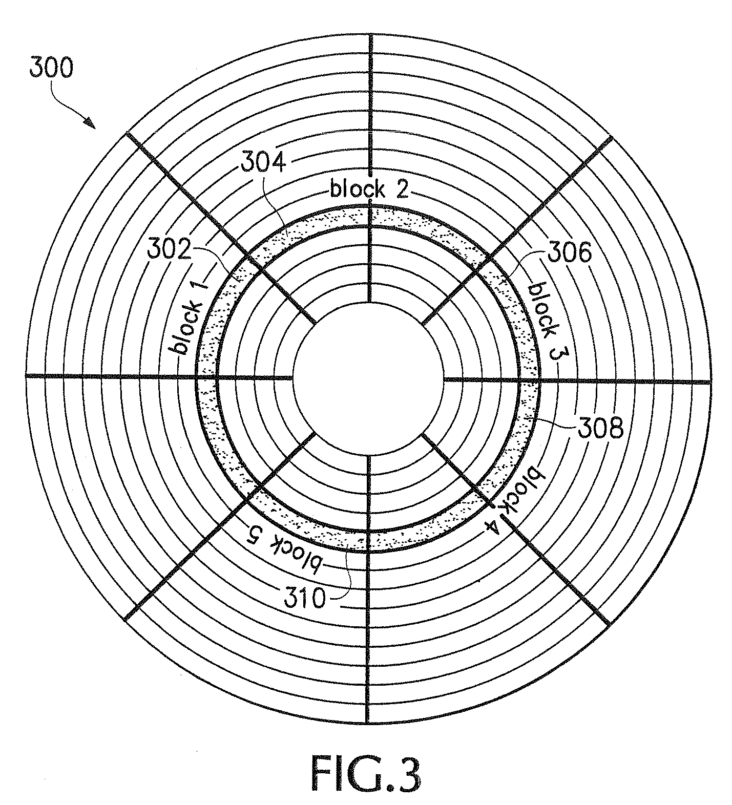
[0021]In the following description, numerous specific details are given to provide a thorough understanding of the invention. However, it will be apparent that the invention may be practiced without these specific details. In order to avoid obscuring the present invention, some well-known circuits, system configurations, and process steps are not disclosed in detail. Likewise, the drawings showing embodiments of the apparatus / device are semi-diagrammatic and not to scale and, particularly, some of the dimensions are for the clarity of presentation and are shown greatly exaggerated in the drawing FIGS. The same numbers are used in all the drawing FIGS. to relate to the same elements.

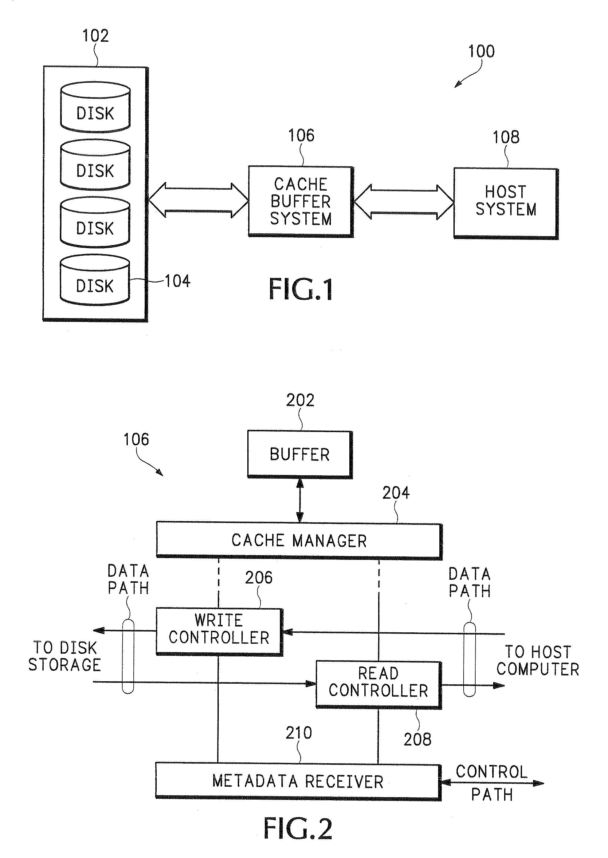
[0022]Referring now to FIG. 1, therein is shown a block diagram of a disk drive storage defragmentation system 100 in an embodiment of the present invention. The block diagram of the disk drive storage defragmentation system 100 depicts a disk drive storage system 102, having multiple instances of a stora...


PUM


Abstract

The present invention provides a disk drive storage defragmentation system, comprising providing a cache buffer system coupled to a host system, coupling a disk drive storage system to the cache buffer system, performing a defragmantation process on the disk drive storage system utilizing the cache buffer system and servicing a data access request by the host system from the cache buffer system.

Description

TECHNICAL FIELD[0001]The present invention relates generally to disk drive storage systems, and more particularly to a system for defragmentation of file systems on disk drive storage systems.BACKGROUND ART[0002]Disk drive based storage systems are widely used for storing digital data of all kinds, such as computer data and multimedia data (voice, video and image). In storage systems, one or more disk drives are configured to provide storage of data content. The disk drives can be read from or written to. Data can be stored and modified on the disk drives via the computer host bus controllers. Before data is stored onto storage systems, it must be organized in logic units, called data files, such as video files, image files, database files, etc. Such organization is typically handled by the operating systems of the computer system that hosts the data files.[0003]In general disk storage system can not hold data without a file system, rather it holds physical arrays of unspecified dat...

Claims


Application Information

Patent Timeline
Patent Type & Authority Patents(United States)
IPC IPC(8): G06F12/00
CPCG06F3/061G06F3/0656G06F17/30135G06F12/0866G06F3/0676G06F16/1724
Inventor ZHANG, JILIU, HAIN-CHINGDING, JIANGANG
Owner SILICON VALLEY BANK
Why Eureka
Try Eureka