Heavy vehicle

a technology for heavy vehicles and heavy vehicles, applied in the direction of loading/unloading vehicles, electric devices, transportation items, etc., can solve the problems of long time taken for these operations, long and tedious operations involved in mounting and demounting tires in the event of replacement or maintenance, and the manufacture of these vehicles to increase their loading capacity. , to achieve the effect of improving the properties of tires and improving vehicle efficiency

Inactive Publication Date: 2008-11-11
MICHELIN RECH & TECH SA
View PDF10 Cites 0 Cited by
  • Summary
  • Abstract
  • Description
  • Claims
  • Application Information

AI Technical Summary

Benefits of technology

[0018]The inventors thus set themselves the task of improving the properties of the tires of these heavy vehicles in terms of wear with regard to those of current tires, in particular with a view to improving vehicle efficiency.
[0023]According to the invention, the driving axle comprises four tires and preferably the two axially outer tires of the driving axle, which advantageously do not transmit the motive power, have as their only essential function that of bearing part of the load. Such an embodiment makes it possible to reduce the longitudinal stresses arising in particular when the vehicle follows the course of a bend. In fact, when a vehicle comprising at least twin tires follows the course of a bend, the tires which are axially furthest to the outside cover a greater distance if positioned on the outside of the bend and a smaller distance if positioned on the inside of the bend. This phenomenon is accentuated in the context of the invention by the width of the tires.
[0024]Furthermore, according to the invention, the tires are individually associated with a braking device in such a way as to make it possible to slow down or stop this type of vehicle under the best conditions, irrespective of the conditions of use of the vehicle at the moment of braking and, in particular, when the vehicle is on a bend or alternatively when it is on a slope. This association of a braking device with each of the tires also makes it possible to limit wear to the tires and to improve distribution of the wear, caused by braking, between the various tires. The invention thus makes it possible, in fact, to prevent more pronounced wear to certain tires if they were the only ones associated with a braking device. The wear caused by braking is particularly marked in the case of vehicles of the dumper type, which have to follow sloping courses with large loads, requiring long and continuous braking.
[0032]According to other variant embodiments of the invention, when all the tires on the steering axle transmit at least part of the motive power, said steering axle is equipped with one or more devices allowing different speeds of rotation to be imparted to the different tires, said speeds being adapted in particular to limit the wear of the various tires, in particular when taking bends.
[0035]According to this embodiment, the use of electric motors associated with a tire makes it possible to distribute the motive power variably as a function of the tires and of the trajectory followed.

Problems solved by technology

In the case of vehicles, in particular intended for use in mines or quarries for transporting loads, the problems of access and demands of production lead the manufacturers of these vehicles to increase their loading capacity.
The operations involved in mounting and demounting said tires in the event of replacement or maintenance are long and tedious.
The time taken for these operations is consequently long and therefore detrimental to the productivity sought during exploitation of said mines.
In fact, the dimensions of said tires will be limited by transportation thereof, in particular by road widths and bridge headroom.
And more frequent tire changes reduce the efficiency of said vehicles.

Method used


Image

  • Heavy vehicle
  • Heavy vehicle
  • Heavy vehicle

Examples


Embodiment Construction

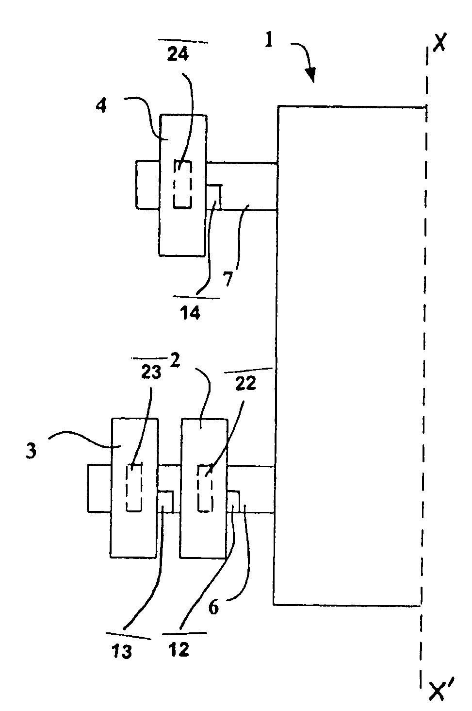
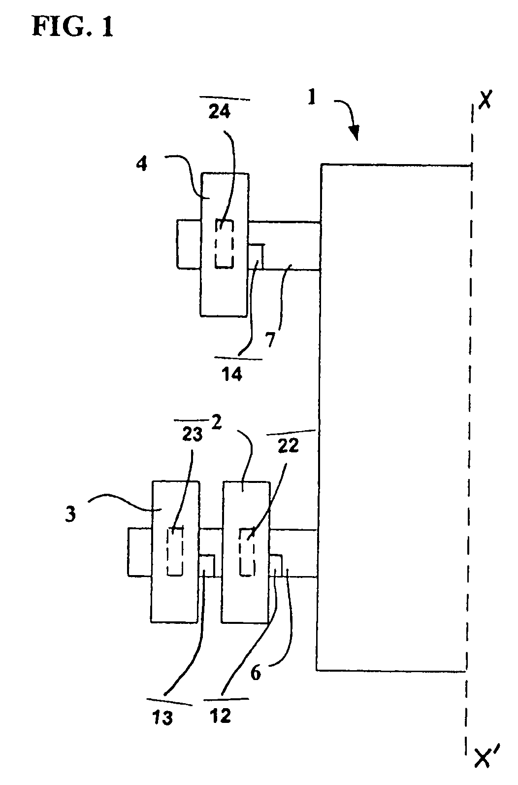
[0042]FIG. 1 is a diagrammatic representation of a half-vehicle 1 configured in accordance with the invention and comprising four tires on the rear driving axle 6 and two steering tires on the front steering axle 7. Since the Figure shows only half of the vehicle, only two tires 2, 3 are shown on the rear axle 6 and one tire 4 on the front axle 7.

[0043]The vehicle 1 shown diagrammatically in this FIG. 1 is a heavy vehicle having a total loaded weight of the order of 600 metric tons.

[0044]The tires with which the vehicle is fitted are large tires whose aspect ratio H / S is 0.80, H being the height of the tire on the rim and S the maximum axial width of the tire when the latter is mounted on its service rim and inflated to its recommended pressure. The tires are of dimension 59 / 80R63.

[0045]These tires comprise a radial carcass reinforcement composed of inextensible metal cables of steel, oriented radically and anchored in each tire bead.

[0046]The tires 2, 3 of the rear axle 6 are mount...


PUM


Abstract

A heavy vehicle of a mass greater than 40 metric tons and operable to generate a motive power is disclosed. The vehicle includes a first axle, at least two first tires mounted on the first axle, a second axle for transmitting at least part of the motive power, and four second tires mounted on the second axle. At most two of the second tires are driving or motive power transmitting tires. Each of the second tires is associated with a respective braking device.

Description

CROSS-REFERENCE TO RELATED APPLICATIONS [0001]This application is a U.S. Continuation Application of International Application PCT / EP2004 / 007661 filed Jul. 12, 2004.BACKGROUND OF THE INVENTION[0002]1. Field of the Invention[0003]The invention relates to a heavy vehicle such as a transport vehicle or a “civil engineering” vehicle, of a mass greater than 40 metric tons.[0004]Although not limited to such applications, the invention will be described more particularly with reference to a heavy vehicle, such as a transport vehicle or a “civil engineering” vehicle, of a mass greater than 500 metric tons, fitted with tires of a diameter greater than three meters fifty having an axial width greater than 37 inches.[0005]2. Description of the Related Art[0006]Such vehicles, generally designed for carrying heavy loads, comprise a front steering axle comprising two steering wheels and a rear axle, which is most frequently rigid, comprising four driving wheels distributed in pairs on each side.[...

Claims


Application Information

Patent Timeline
Patent Type & Authority Patents(United States)
IPC IPC(8): B62D61/10B60P1/00
CPCB60P1/00B62D61/10B60L2220/44B60L2260/28
Inventor DURIF, PIERRE
Owner MICHELIN RECH & TECH SA
Why Eureka
Try Eureka