

Lighting device
a technology of light source and lead wire, which is applied in the direction of lighting and heating apparatus, instruments, optical elements, etc., can solve the problems of increasing manufacturing costs, increasing the frictional resistance generated when each socket is slid along each lead wire, and increasing the bending angle of each lead wire in the substantially l-shaped through-hole. , to achieve the effect of reducing frictional resistance, reducing frictional resistance, and smooth sliding
- Summary
- Abstract
- Description
- Claims
- Application Information
AI Technical Summary
Benefits of technology
Problems solved by technology
Method used
Image

Examples
Embodiment Construction
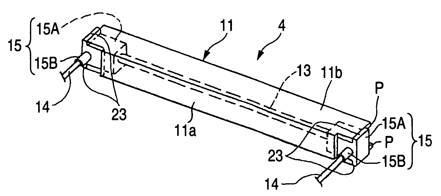
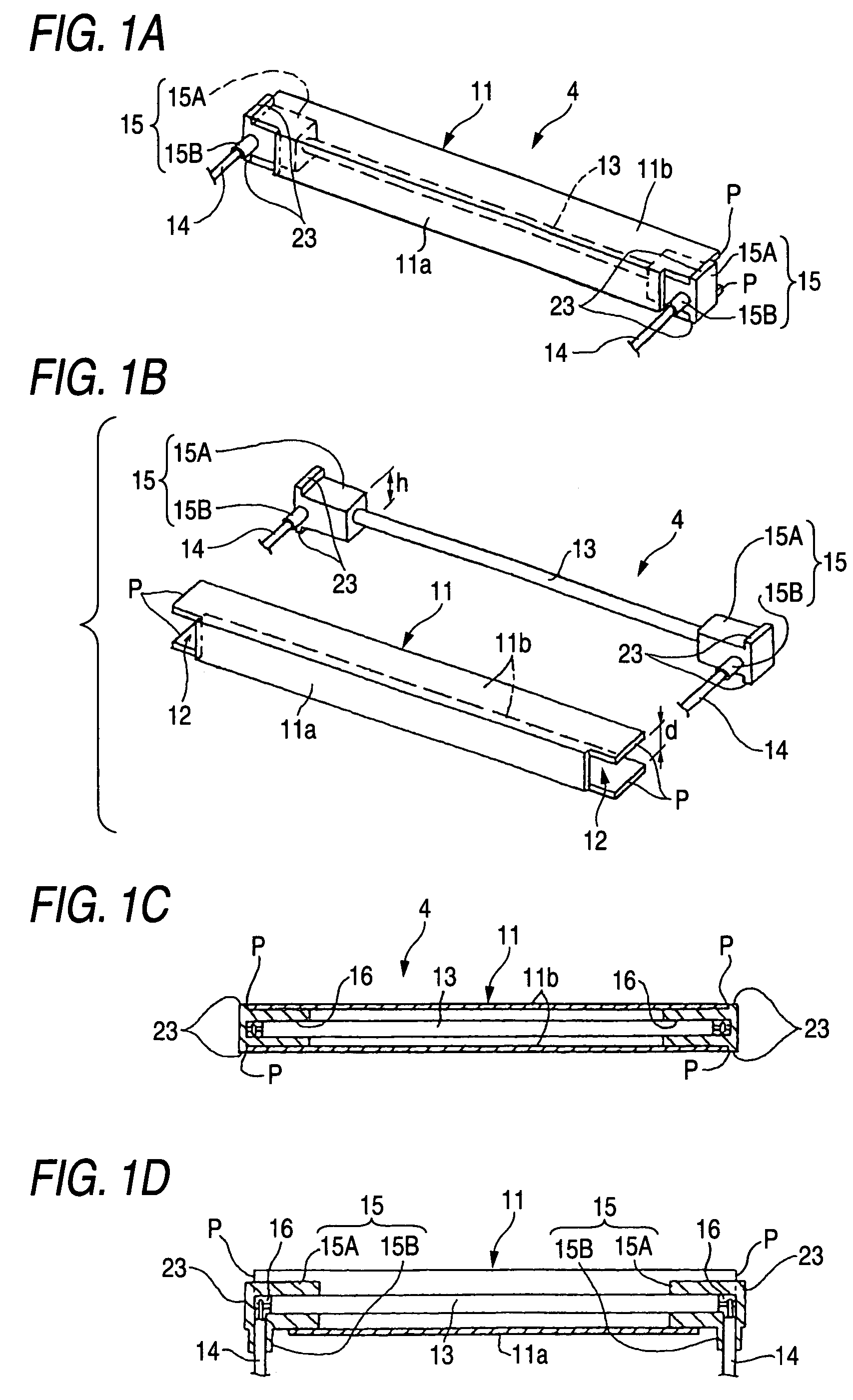
[0028]FIGS. 1A to 2C are views showing a lighting device 4 which is an embodiment of the present invention. This lighting device 4 is incorporated into the liquid crystal module shown in FIGS. 3 and 4. The branch portion 15B of each socket 15 is formed into a thin cylindrical shape which can be elastically displaced. End faces of both side plates 12b of the lamp reflector 11 are the points P for positioning. The positioning protrusions (the positioning portions) 23 are integrally protruded from the outer end edges on both sides of the socket body 15A. Except for the above structure, like reference characters are used to indicate like parts in FIGS. 1A to 2C and FIGS. 3 to 7C, and the same explanations are omitted here.
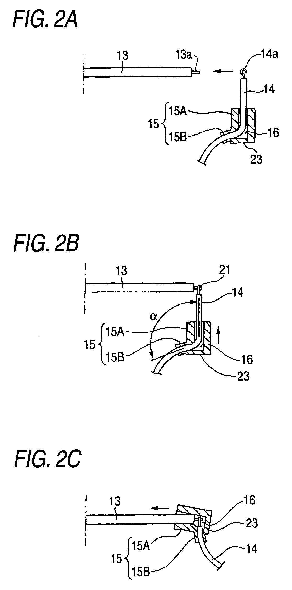
[0029]The procedure of attaching the socket 15 will be explained below. As shown in FIG. 2A, under the condition that the substantially L-shaped through-passage 16 of each socket body 15A is externally engaged with each lead wire 14, as shown in FIG. 2B, the end portio...
PUM
 Abstract
Description
Claims
Application Information