Method of forming cord-reinforced tire structural member

a technology of cord reinforcement and structural parts, which is applied in the direction of tyres, chemistry apparatus and processes, lamination ancillary operations, etc., can solve the problems of reducing the affecting the production efficiency of tyres, etc., to achieve the effect of reducing the production cost, simplifying the manufacturing of the tire structural member, and facilitating the manufacture of tires

Inactive Publication Date: 2008-11-11
BRIDGESTONE CORP
View PDF12 Cites 0 Cited by
  • Summary
  • Abstract
  • Description
  • Claims
  • Application Information

AI Technical Summary

Benefits of technology

[0010]Thus, the tire structural member is formed by successively arranging a predetermined number, which corresponds to a tire size, of the strips and joining together side edge parts of the strips. Therefore, the tire structural member thus formed by the simple method is provided with the number of the cords accurately corresponding to a number specified for a tire size. Since the number of the cords in the tire structural member is accurately fixed, the weight and the cost of the tire do not increase, and the dynamic balance and the uniformity of the tire can be improved.
[0012]When the tire has a size of n in., the n strips of π in. in width are connected successively to form the tire structural member for the tire. Thus, the strips of about π in. in width facilitate manufacturing the tire. A tire structural member forming apparatus for manufacturing the tire structural member is simplified and can be formed in a small size to manufacture the tire structural member at low manufacturing cost.

Problems solved by technology

Since the cords are arranged at very small pitches slightly smaller than 1 mm, the pitches of the cords are liable to include errors.
Since errors in the pitches of the cords are accumulated in each of the plies, it is difficult to form the plies having the same number of the cords.
Thus, errors in the pitch of the cords of the ply sheet wound in the large roll tend to increase and hence it is very difficult to form the plies of the same length having the same number of cords.
The weight of the tire increases and material cost increases if the number of the cords in the plies is excessively large.

Method used


Image

  • Method of forming cord-reinforced tire structural member
  • Method of forming cord-reinforced tire structural member
  • Method of forming cord-reinforced tire structural member

Examples


Embodiment Construction

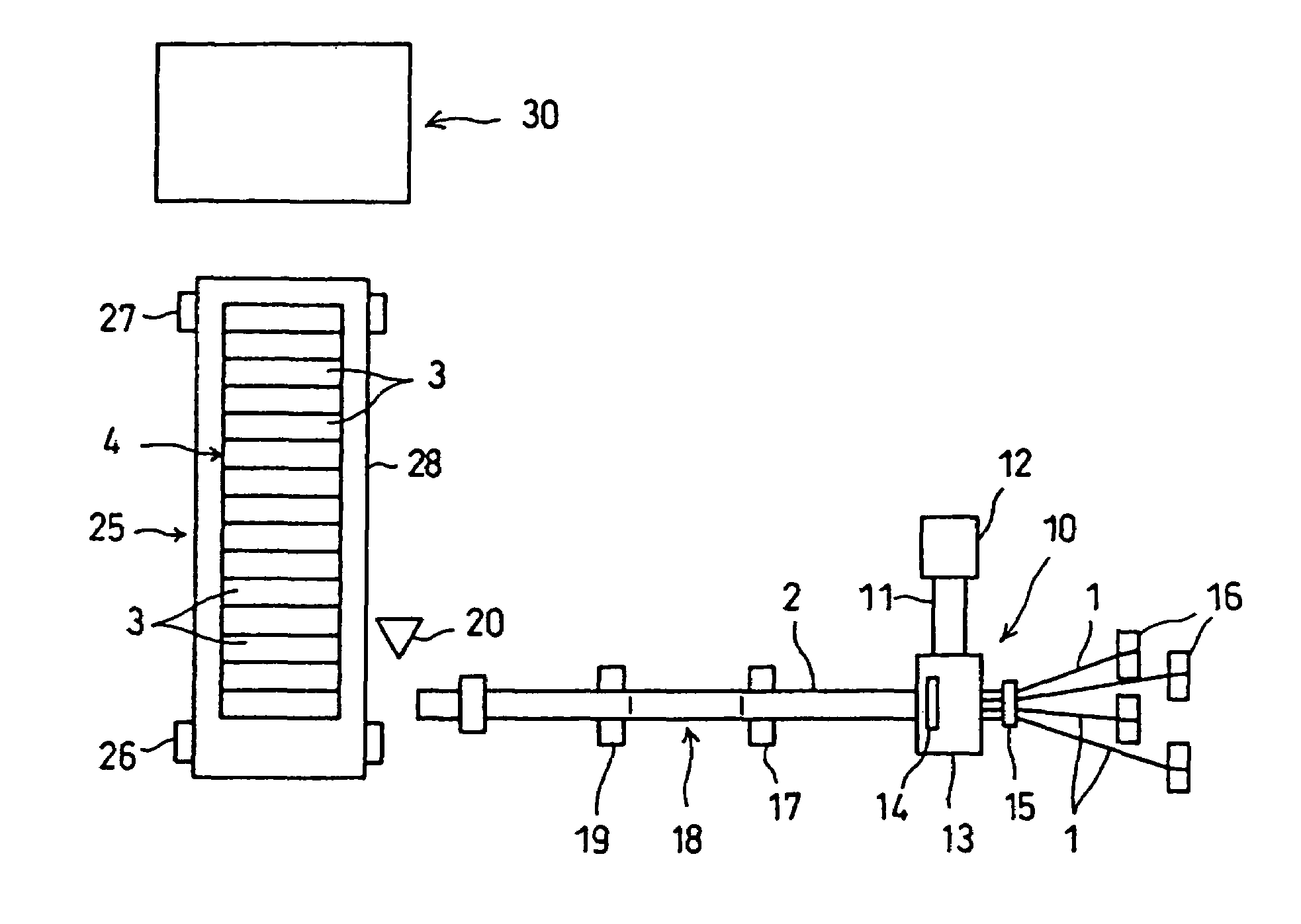
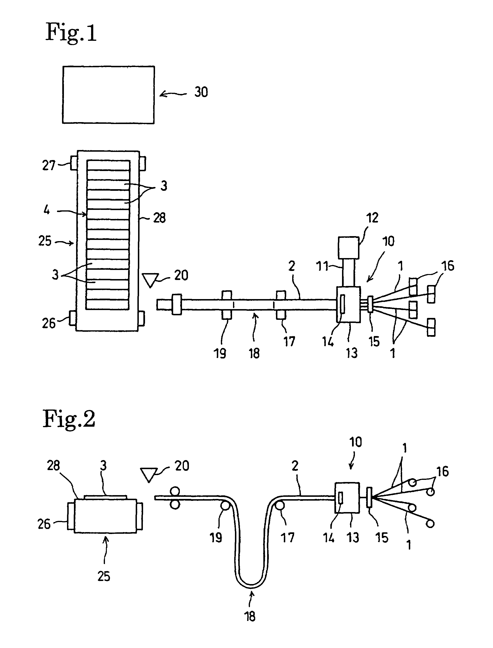
[0024]A method of forming a cord-reinforced tire structural member in a preferred embodiment of the present invention will be described with reference to FIGS. 1 to 6.

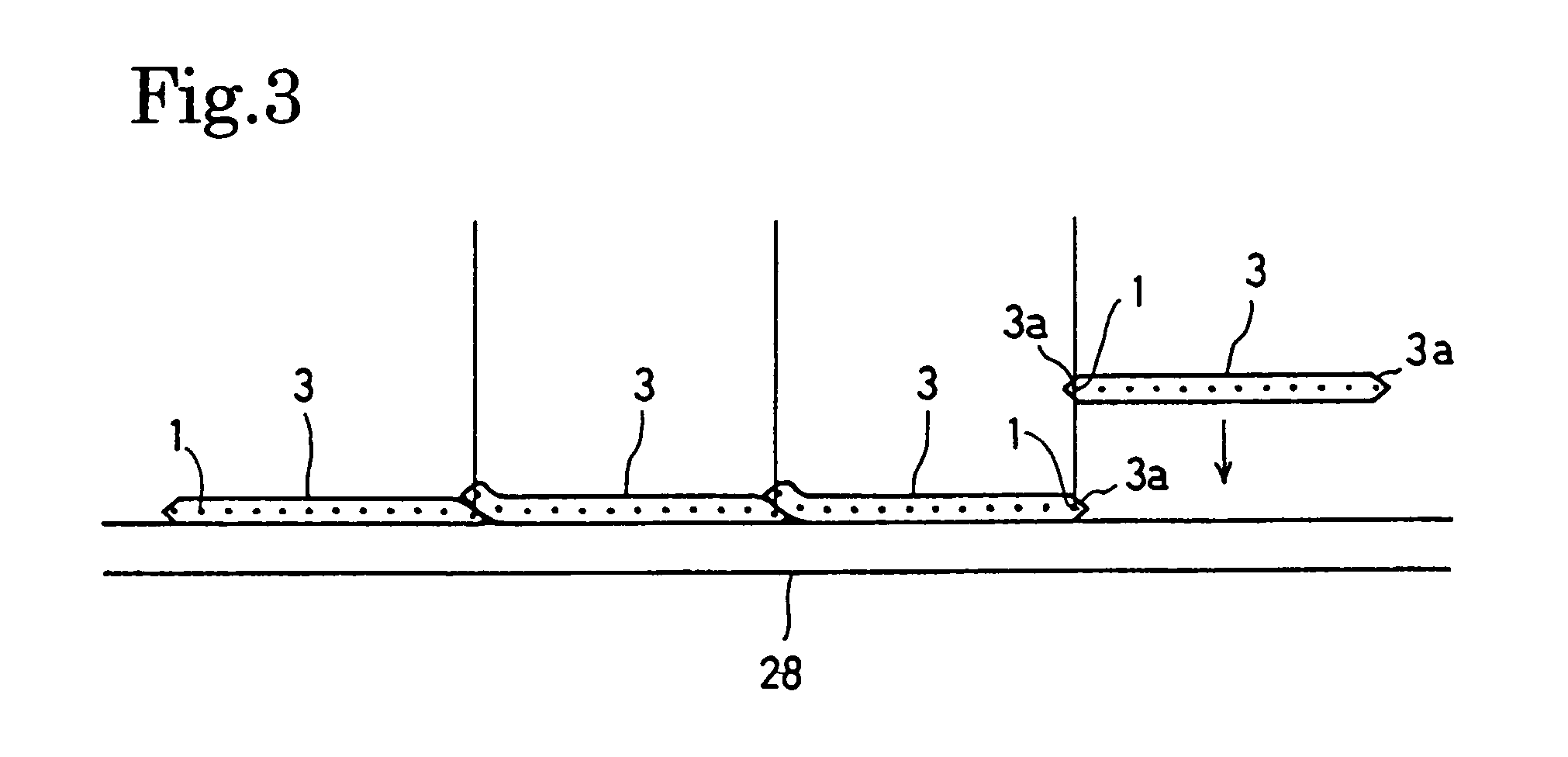
[0025]Actually the method of forming a cord-reinforces tire structural member in this embodiment is a ply forming method of forming a ply, namely, a tire structural member. FIGS. 1 to 3 show a ply manufacturing system for carrying out the ply forming method.

[0026]An extruder 10 for extruding a rubber compound has a cylinder 11 internally provided with a screw, not shown, and a hopper 12 connected to the cylinder 11 to feed a material, namely, a rubber compound, into the cylinder 11. The screw is rotated to knead the rubber compound fed into the cylinder 11 and to carry the rubber compound through the front end of the cylinder 11 to a die 14 of a predetermined shape held in an insulation head 13.

[0027]An inserter 15 is disposed behind the die 14 of the insulation head 13 of the extruder 10. A plurality of cords 1, such ...


PUM

PropertyMeasurementUnit
diameteraaaaaaaaaa
diameteraaaaaaaaaa
diameteraaaaaaaaaa

Abstract

A cord-reinforced tire structural member is formed by successively arranging strips of a predetermined width w of about π in. and bonding together edge parts of adjacent strips 3. The number of cords included in each of the strips 3 is determined for the type of the cords. A tire structural member 4 is formed by successively arranging a number of the strips 3, equal to a tire size in inch in a direction parallel to the width of the strips and bonding together edge parts of adjacent strips 3. Thus, the number of cords to be included in the tire structural member 4 for one tire can be easily fixed.

Description

FIELD OF THE INVENTION[0001]The present invention relates to a method of forming a cord-reinforced tire structural member.BACKGROUND ART[0002]A prior art method of forming a cord-reinforced tire structural member, such as a ply or a belt, disclosed in, for example, JP 2000-159399 A includes a coating process of coating cords with a rubber compound to form a cord-reinforced rubber belt, a cutting process of cutting the cord-reinforced rubber belt into strips of a length corresponding to the length of a section of a tire, and a tire structural member sheet forming process of successively arranging the strips such that the side edges of adjacent strips overlap each other to form a ply sheet or a belt sheet. The ply or belt sheet is wound in a large roll for storage. The large roll of the ply sheet or belt sheet is then sent to a ply or belt forming process. The ply or belt forming process cuts the ply sheet or belt sheet into plies or belts of a predetermined length conforming to the s...

Claims


Application Information

Patent Timeline
Patent Type & Authority Patents(United States)
IPC IPC(8): B29D30/38B29D30/42B29D30/46
CPCB29D30/38B29D30/42Y10T156/1075B29D2030/421Y10S156/906B29D2030/381B29D2030/705
Inventor SUDA, NOBUYUKI
Owner BRIDGESTONE CORP
Why Eureka
Try Eureka