Apparatus for the operation of a microfluidic device

a microfluidic device and apparatus technology, applied in the direction of instruments, separation processes, laboratory glassware, etc., can solve the problem of relative difficulty in handling

Inactive Publication Date: 2008-11-11
CAPLIPER LIFE SCI INC +1
View PDF25 Cites 58 Cited by
  • Summary
  • Abstract
  • Description
  • Claims
  • Application Information

AI Technical Summary

Problems solved by technology

In this context it must particularly be taken into account that the microchips exhibit dimensions of only a few millimeters up to the order of magnitude of a centimeters, and are thus relatively difficult to handle.

Method used


Image

  • Apparatus for the operation of a microfluidic device
  • Apparatus for the operation of a microfluidic device
  • Apparatus for the operation of a microfluidic device

Examples


Embodiment Construction

I. Microchip Laboratory Systems

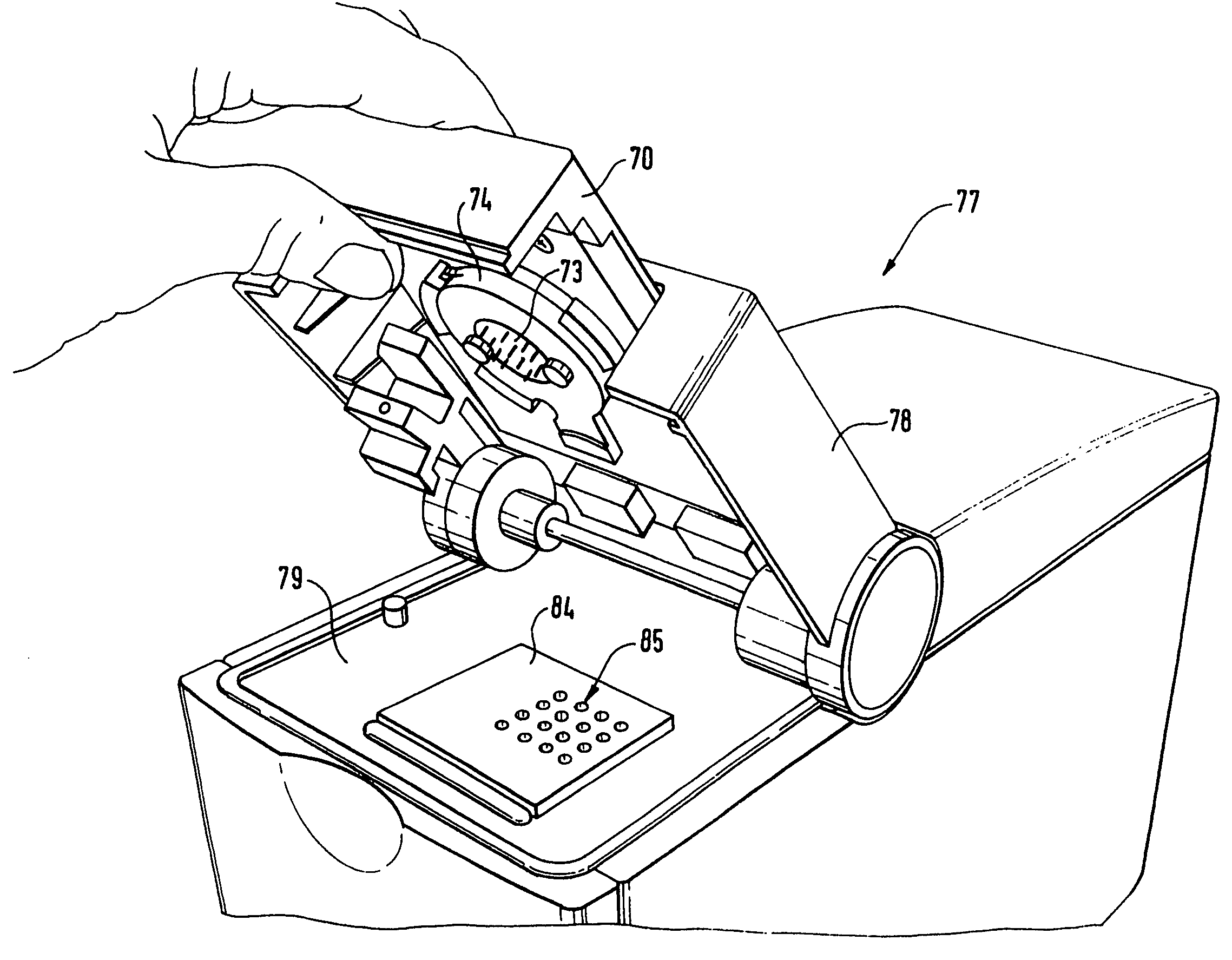
[0016]The present invention relates in general to microchip laboratory systems used in the controlled implementation of chemical, physicochemical, physical, biochemical and / or biological processes. More specifically the present invention relates to microchip laboratory systems for the analysis or synthesis of materials, and particularly fluid borne materials, within a microfluidic device or structure, by electrical, electromagnetic or similar means. In particular, the invention relates to a system for the operation and handling of a laboratory microchip. In general, the invention comprises a means or region for mounting of the microchip and means or interface for providing a potential required for the microfluidic transportation of materials on the microchip. As used herein, the term “potential” generally refers to an energy potential that may be supplied by, e.g., electrical sources, pressure sources, thermal sources or the like. The region for mounti...


PUM

PropertyMeasurementUnit
surfaces resistantaaaaaaaaaa
electrical energyaaaaaaaaaa
mechanical energyaaaaaaaaaa

Abstract

In a system for operation or handling of a laboratory microchip (41) for chemical processing or analysis, the microchip (41) is mounted in a first physical unit (42). The microchip (41) is arranged on a mounting plate, such that it is readily accessible from the top and thus the fitting and removal of the microchip is considerably simplified. Furthermore, the first physical unit (42) comprises an optical device (43) for contactless detection of the results of the chemical processes conducted on the microchip. The supply systems necessary for the operation of the microchip are arranged in a module unit that has a separable connection with a second physical unit. The proposed modular layout enables ease of interchangeability of the required supply systems and thus, overall, ease of adaptability of the proposed system for various types of microchips.

Description

CROSS REFERENCE TO RELATED APPLICATION[0001]This application is a continuation of U.S. patent application Ser. No. 09 / 595,420, filed Jun. 15, 2000, now U.S. Pat. No. 6,811,668 which is an application claiming the benefit under 35 USC 119(e) to U.S. Provisional Patent Application No. 60 / 140,215, filed Jun. 22, 1999, which is hereby incorporated herein by reference in its entirety for all purposes.BACKGROUND OF THE INVENTION[0002]Microfluidic devices and systems are gaining wide acceptance as alternatives to conventional analytical tools in research and development laboratories in both academia and industry. This acceptance has been fueled by rapid progress in this technology over the last several years.[0003]The rapid progress in this field can best be illustrated by analogy to corresponding developments in the field of microelectronics. In the field of chemical analysis, as in microelectronics, there is a considerable need for integration of existing stationary laboratory installati...

Claims


Application Information

Patent Timeline
Patent Type & Authority Patents(United States)
IPC IPC(8): G01N27/453B01L3/00C02F1/40C02F11/00C25B11/00C25B13/00G01N27/27G01R1/00
CPCB01L3/502715B01L2200/027B01L2200/10B01L2300/0819B01L2400/0421
Inventor BERNDT, MANFREDKALTENBACH, PATRICKKENNEDY, COLIN B.
Owner CAPLIPER LIFE SCI INC
Why Eureka
Try Eureka