
Power over ethernet controller suitable for multiple modes

a technology of power over ethernet controller and multiple modes, which is applied in the field of remote powering, can solve the problems of not being designed to support such an architecture, no provision has been made in the above standard, and the above standard is limited to a powered device (pd), so as to increase the power level over two twisted wire pairs, and not increase the power handling capabilities of a single integrated switch

Active Publication Date: 2008-11-11
CISCO TECH INC
View PDF7 Cites 26 Cited by
  • Summary
  • Abstract
  • Description
  • Claims
  • Application Information

AI Technical Summary

Benefits of technology

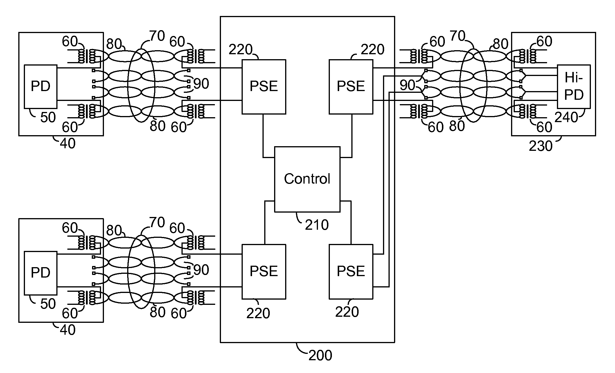
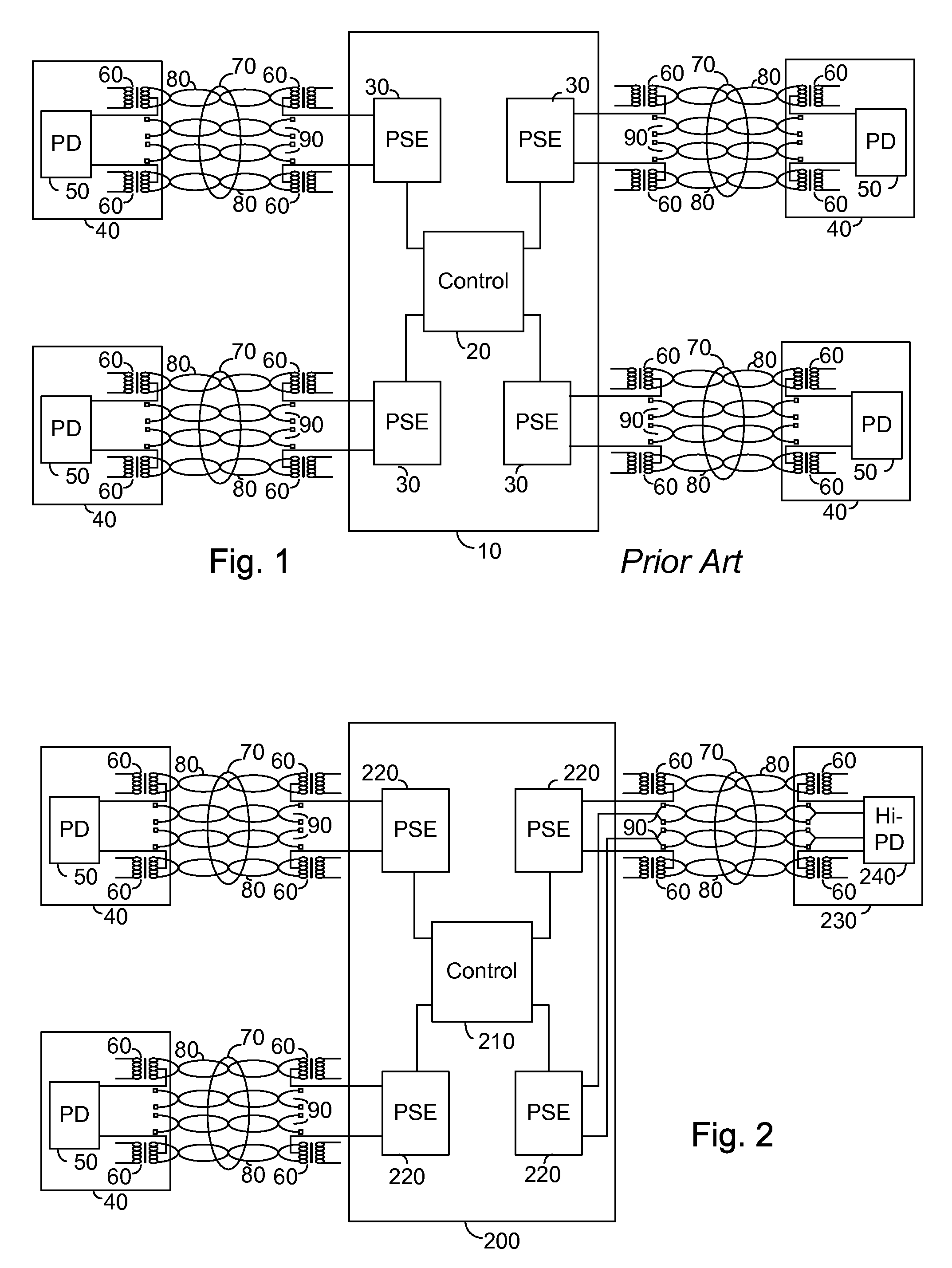
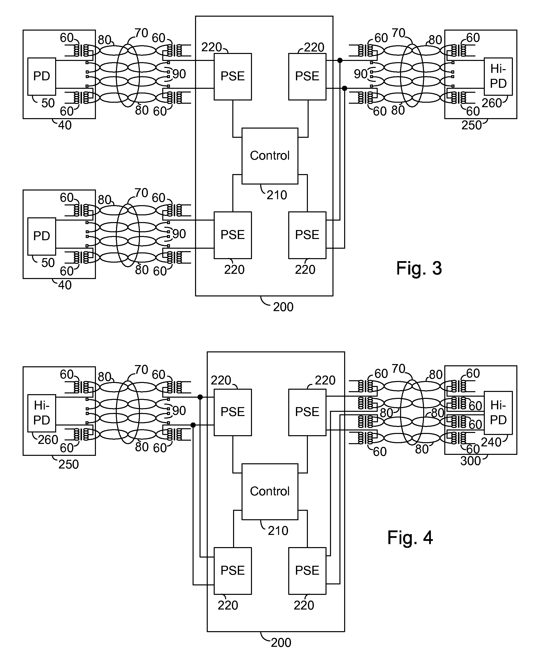
[0011]In the first mode the control circuit operates two ports as a single PSE. In an exemplary embodiment the power outputs are connected together and the real time activities including: detection, classification, and port status monitoring are activated for only one of the two ports. Thus, the two integrated switches are effectively operated in parallel enabling a doubling of the power output while real time activities are performed as a single unit. As a result, an increased power level over two twisted wire pairs is supported without increasing the power handling capabilities of a single integrated switch.

Problems solved by technology

The above standard is limited to a powered device (PD) having a maximum power requirement during operation of 12.95 watts.
Unfortunately, no provision has been made in the above standard for PDs requiring power in excess of the above maximum power requirement.
The above power limitation is primarily a function of the power carrying capabilities of the installed twisted wire pairs being utilized to deliver power.
Unfortunately, commercially available PoE controllers, such as the one described above, are not designed to support such an architecture.
Such an increased power will however be in excess of the design constraints of many of today's integrated PoE controllers, which exhibit integrated switches having thermal constraints.

Method used


Image

  • Power over ethernet controller suitable for multiple modes
  • Power over ethernet controller suitable for multiple modes
  • Power over ethernet controller suitable for multiple modes

Examples


Embodiment Construction

[0035]The present embodiments enable a PoE controller exhibiting switches having a powering limit less than that required for increased power levels over two twisted wire pairs. The PoE controller further comprises a control circuit operable in a plurality of modes, a first of whose modes supports increased power levels over two twisted wire pairs and a second of whose modes supports power over four twisted wire pairs.

[0036]In the first mode the control circuit operates two ports as a single PSE. In an exemplary embodiment the power outputs are connected together and the real time activities including: detection, classification, and port status monitoring are activated for only one of the two ports. Thus, the two integrated switches are effectively operated in parallel enabling a doubling of the power output while real time activities are performed as a single unit. As a result, an increased power level over two twisted wire pairs is supported without increasing the power handling c...


PUM


Abstract

A power over Ethernet controller supporting a plurality of powering modes, the power over Ethernet controller comprising: a pair of power sourcing equipments; and a control circuit; the control circuit being operative to control each of the pair of power sourcing equipment units in one of a first mode and a second mode, the first mode comprising operating the pair of power sourcing equipments as a single power sourcing equipment operable to power a single powered device over communication cabling, and the second mode comprising operating each of the power sourcing equipments of the pair independently so as to each be operable to power an associated powered device over communication cabling.

Description

CROSS REFERENCE TO RELATED APPLICATIONS[0001]This application claims priority from U.S. Provisional Patent Application Ser. No. 60 / 704,242 filed Aug. 1, 2005 entitled “Power Over Ethernet Controller Suitable for Multiple Modes” the entire contents of which is incorporated herein by reference. This application is a continuation in part of: U.S. patent application Ser. No. 10 / 761,327 filed Jan. 22, 2004 entitled “High Power Architecture for Power Over Ethernet”; U.S. patent application Ser. No. 11 / 036,063 filed Jan. 18, 2005 entitled “High Power Architecture for Power Over Ethernet”; and U.S. patent application Ser. No. 11 / 218,607 filed Sep. 6, 2005 entitled “Redundant Powered Device Circuit”, the entire contents of each of which are incorporated herein by reference.BACKGROUND OF THE INVENTION[0002]The present invention relates to the field of remote powering and more particularly to a power over Ethernet controller supporting high power over both two twisted wire pairs and four twist...

Claims


Application Information

Patent Timeline
Patent Type & Authority Patents(United States)
IPC IPC(8): H04B3/54H02J3/38
CPCH04L12/10
Inventor ELKAYAM, SHIMONOHANA, ELIKORCHARZ, DROR
Owner CISCO TECH INC
Learn More