Vacuum pump and method for generating sub-pressure

a vacuum pump and sub-pressure technology, applied in non-positive displacement pumps, mechanical equipment, liquid fuel engines, etc., can solve problems such as obstructing a free decentralization of vacuum sources

Inactive Publication Date: 2008-11-18
PIAB
View PDF14 Cites 22 Cited by
  • Summary
  • Abstract
  • Description
  • Claims
  • Application Information

AI Technical Summary

Problems solved by technology

However, in certain applications operated by sub-pressure, the elevated temperature in the compressed discharge air from a screw-rotor pump may obstruct a free de-centralization of vacuum sources.

Method used


Image

  • Vacuum pump and method for generating sub-pressure
  • Vacuum pump and method for generating sub-pressure
  • Vacuum pump and method for generating sub-pressure

Examples


Embodiment Construction

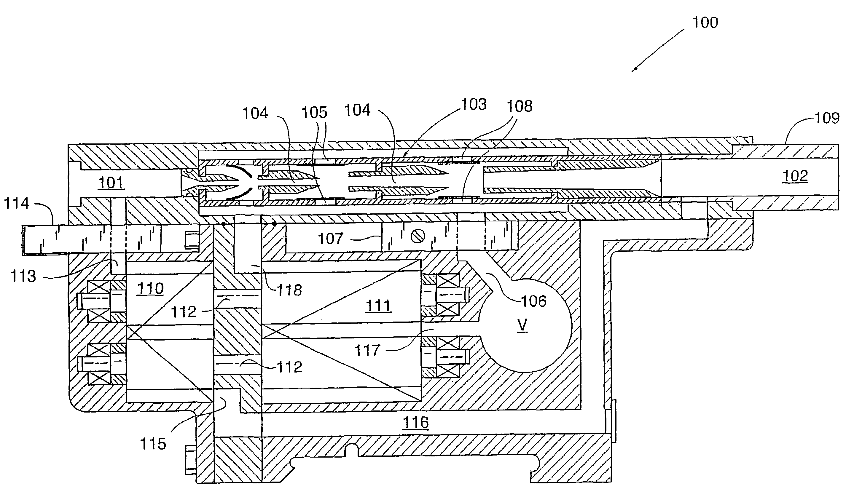
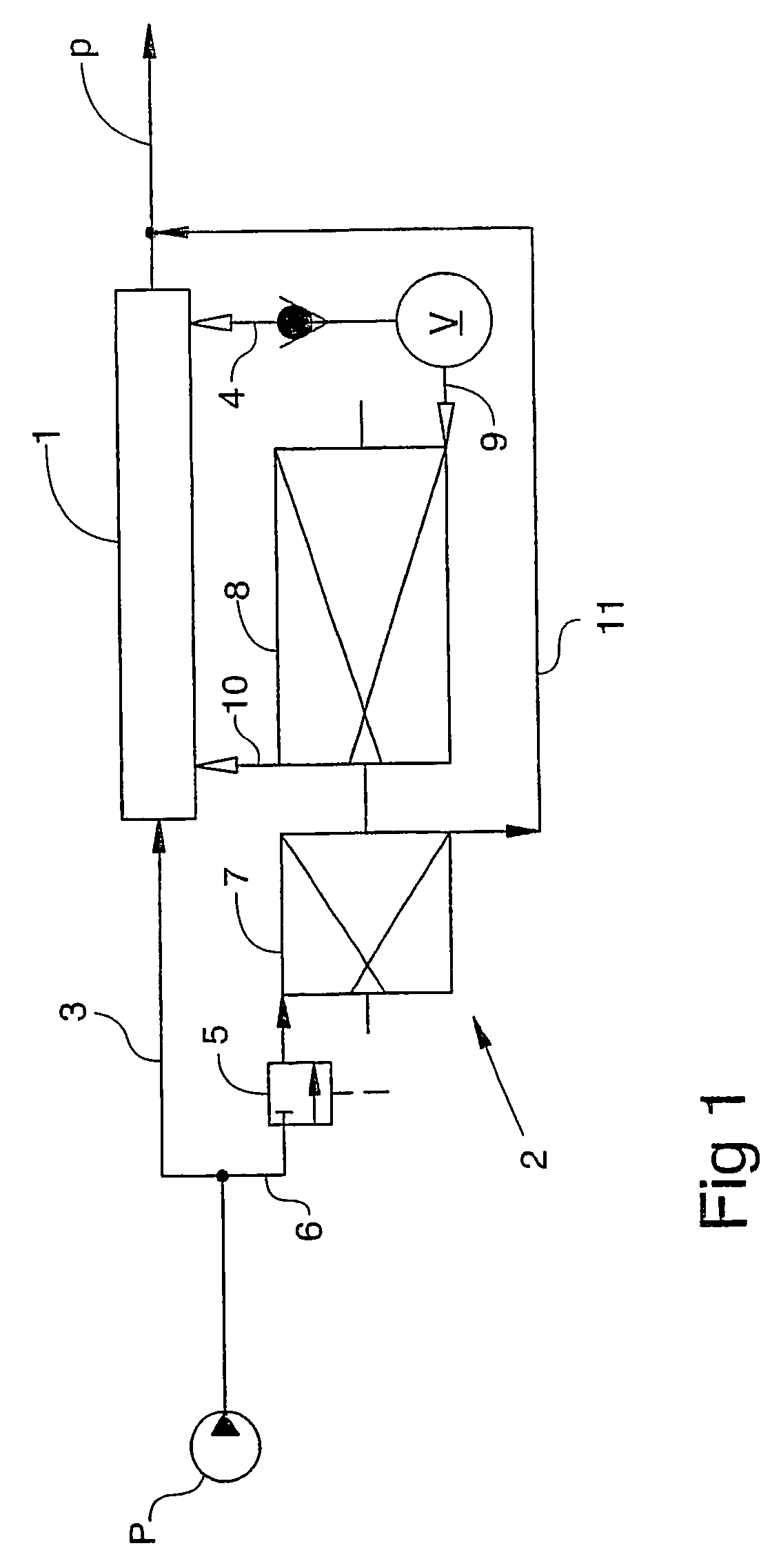
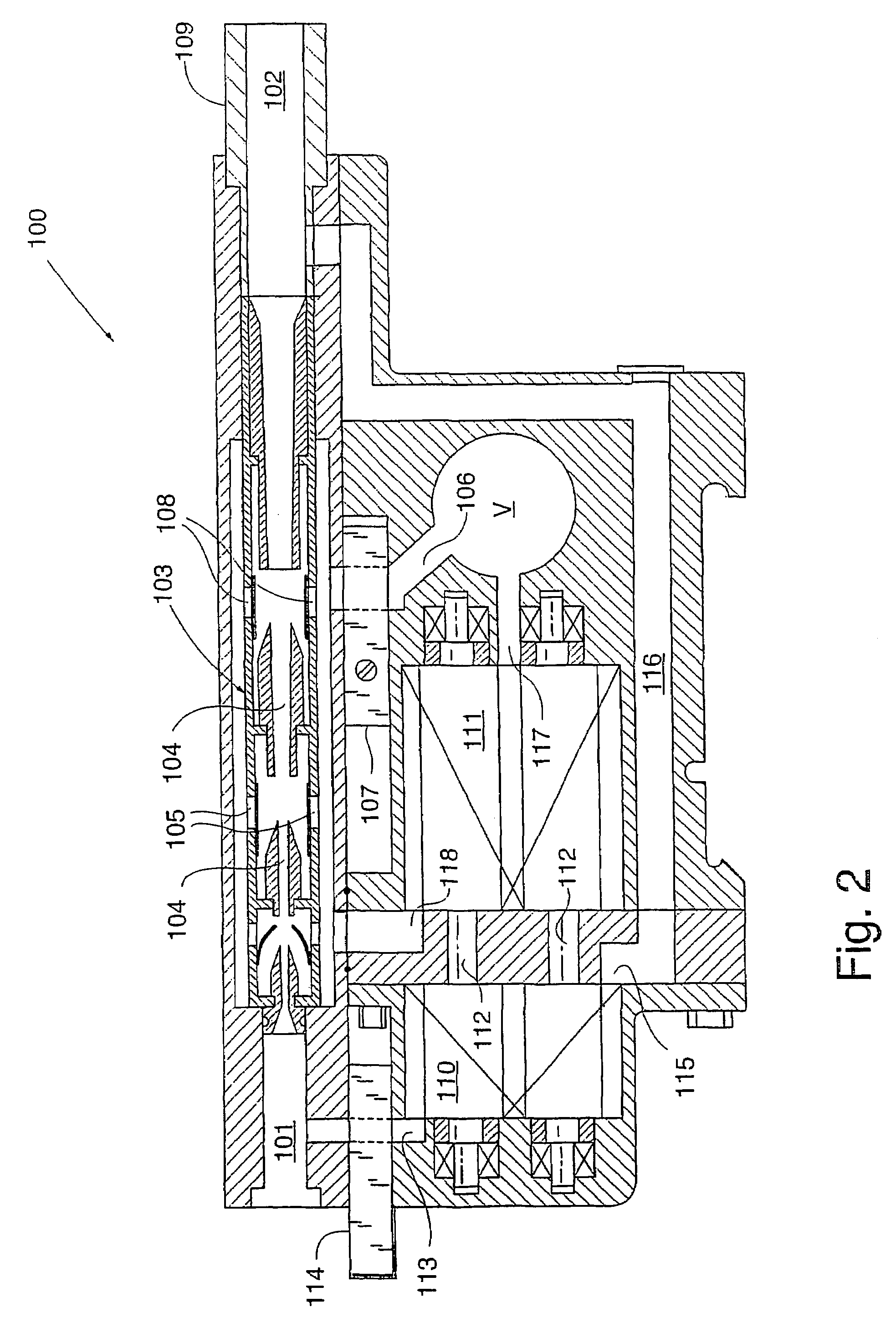
[0016]With reference to FIG. 1, a vacuum pump is diagrammatically shown to comprise a screw-rotor pump 2 in integration with at least one ejector 1. For example, the ejector 1 may be a multi stage ejector operated by compressed air from a high pressure source P, via the line 3. While expanded through the ejector's nozzles, the compressed air or other drive-gas generates a sub-pressure that causes flap valves in the ejector ports to open and communicate with an evacuation chamber V, via a line 4. The drive-gas and the evacuated gas or air is discharged from the ejector mouth as illustrated by an arrow p.

[0017]Starting from a predetermined pressure level below atmosphere, the screw-rotor pump 2 is arranged to operate in parallel with the ejector 1. To this purpose, an electrically operated compressed-air valve 5 is arranged to supply drive-gas to the screw-rotor pump via a line 6 as the pressure in the evacuated chamber V is reduced to a predetermined lower level, such as about 300 mb...


PUM


Abstract

According to the invention, a vacuum pump is disclosed comprising a screw-rotor pump having a compression section (8) and an expansion section (7), and wherein a discharge (10) from the compression section communicates with at least one ejector (1) for discharge of compressed gas through the ejector, and wherein the expansion section (7) is connectable via a first valve means (5), to a drive-gas source (P) for operating the screw,-rotor pump and the ejector in parallel. Also, a method for providing sub-pressure to an industrial process is disclosed wherein at least one ejector (1) is used initially to reduce the pressure to a predetermined lower level, from where the pressure is further reduced by means of a screw-rotor pump (7, 8) that is arranged to operate through, and in parallel with the ejector.

Description

TECHNICAL FIELD[0001]The subject invention refers to a pump for generating sub-pressure or vacuum, the pump comprising a screw-rotor type pump in integration with an ejector. In accordance herewith, the invention also refers to a method for providing sub-pressure to an industrial process.BACKGROUND AND PRIOR ART[0002]For example, vacuum pumps of the screw-rotor type are previously known from SE 0002129-5 (Svenska Rotor Maskiner AB). Screw-rotor pumps of that type comprises a compression section wherein intermeshing rotor bodies are rotated for compression of a gas that is drawn in between the rotating bodies. The compression section is driven by an expansion section having intermeshing rotor bodies that are caused to rotate through the expansion of a drive gas, such as compressed air, that is introduced in the expansion section.[0003]Vacuum pumps of the ejector type, driven by compressed air for generating a sub-pressure, are previously known from SE 9800943-4 (PIAB AB), e.g. The ej...

Claims


Application Information

Patent Timeline
Patent Type & Authority Patents(United States)
IPC IPC(8): F04B23/14F04B23/08F04F5/22F04C23/00F04C25/02F04C29/12F04F5/54
CPCF04C25/02F04F5/22F04C18/16F04C23/005F04F5/54F04C23/00
Inventor TELL, PETER
Owner PIAB
Why Eureka
Try Eureka