Transverse tape application method and apparatus

a technology of tape and tabs, applied in the directions of packaging, labelling, transportation and packaging, etc., can solve the problem of almost unnoticeable cutting noise level, remove or reduce the level of vacuum, and reduce the moment of inertia of tape segments , the coefficient of friction between the protuberances and the traveling web is relatively high

Active Publication Date: 2008-11-18
CURT G JOA
View PDF439 Cites 50 Cited by
  • Summary
  • Abstract
  • Description
  • Claims
  • Application Information

AI Technical Summary

Benefits of technology

[0012]The invention provides the additional benefit of quiet operation compared to prior art equipment, which uses high speed cutting faces and suffers from the effects of the very high energy levels seen at the point of contact. Generally, these energies, and the sounds that they generate, increase in proportion to the square of the velocity. The present invention benefits from the relatively low speed of the cutting faces and exhibits extremely low noise levels. In fact, the underlying noise of the mechanical drive systems and the traveling web equipment contribute to make the cutting noise level nearly unnoticeable.
[0015]Given the extremely low moment of inertia of the tape segments and the aggressive adhesion provided between its exposed adhesive and the compatible surface of the traveling web, each successive segment is successfully transferred to the traveling web, accelerating almost instantly to the speed of the traveling web.
[0016]A key aspect of this invention lies in the method and apparatus used to affect the transfer of the tape segments from the anvil to the traveling web. In accordance with the invention, a vacuum commutation system is configured to remove or reduce the level of vacuum used to hold each tape segment to the anvil surface just before the point of transfer. The materials and finishes selected for the anvil and the transfer protuberances provide a situation in which the coefficient of friction between the protuberances and the traveling web is relatively high, while the coefficient of friction between the tape segment and the anvil is relatively low. The highly aggressive nature of the bond between the adhesive side of the tape segment and the target surface of the traveling web ensures that there is virtually no slippage between the two. This ensures that the traveling web is driven through the point of transfer at its existing velocity, and that any tendency of the tape segment to adhere to the anvil surface will not influence the traveling web. The process requires that some slip occurs, and in accordance with the invention, slip occurs only between the tape segment and the anvil surface.

Problems solved by technology

In fact, the underlying noise of the mechanical drive systems and the traveling web equipment contribute to make the cutting noise level nearly unnoticeable.

Method used


Image

  • Transverse tape application method and apparatus
  • Transverse tape application method and apparatus
  • Transverse tape application method and apparatus

Examples


Embodiment Construction

[0024]Although the disclosure hereof is detailed and exact to enable those skilled in the art to practice the invention, the physical embodiments herein disclosed merely exemplify the invention which may be embodied in other specific structure. While the preferred embodiment has been described, the details may be changed without departing from the invention, which is defined by the claims.

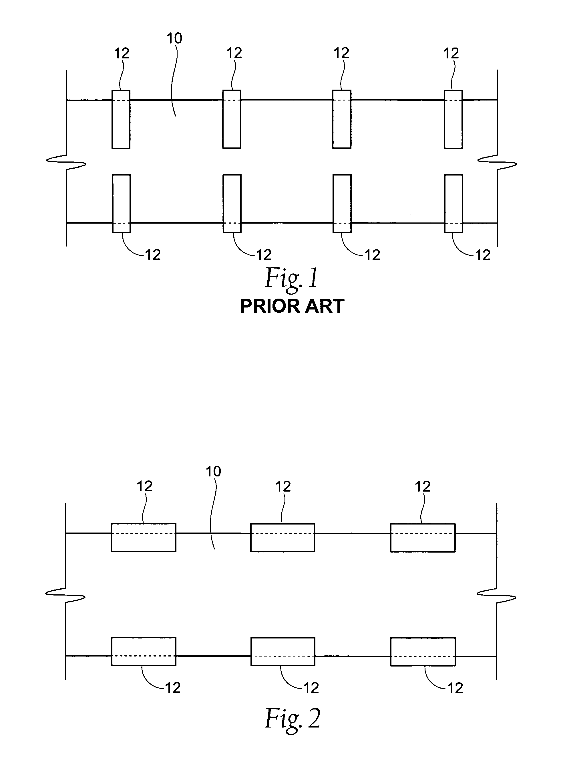
[0025]FIG. 1 shows an overhead view of a web of traveling material 10 having tape tabs 12 applied to the web 10 according to the prior art. The tape tabs 12 are applied from an anvil carrying an adhesive material (not shown) that rotates in the same direction as the movement of the web 10. The tabs 12 are placed so that the tabs 12 are attached perpendicular to the web 10.

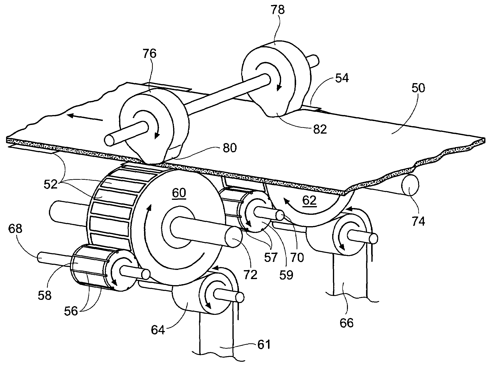
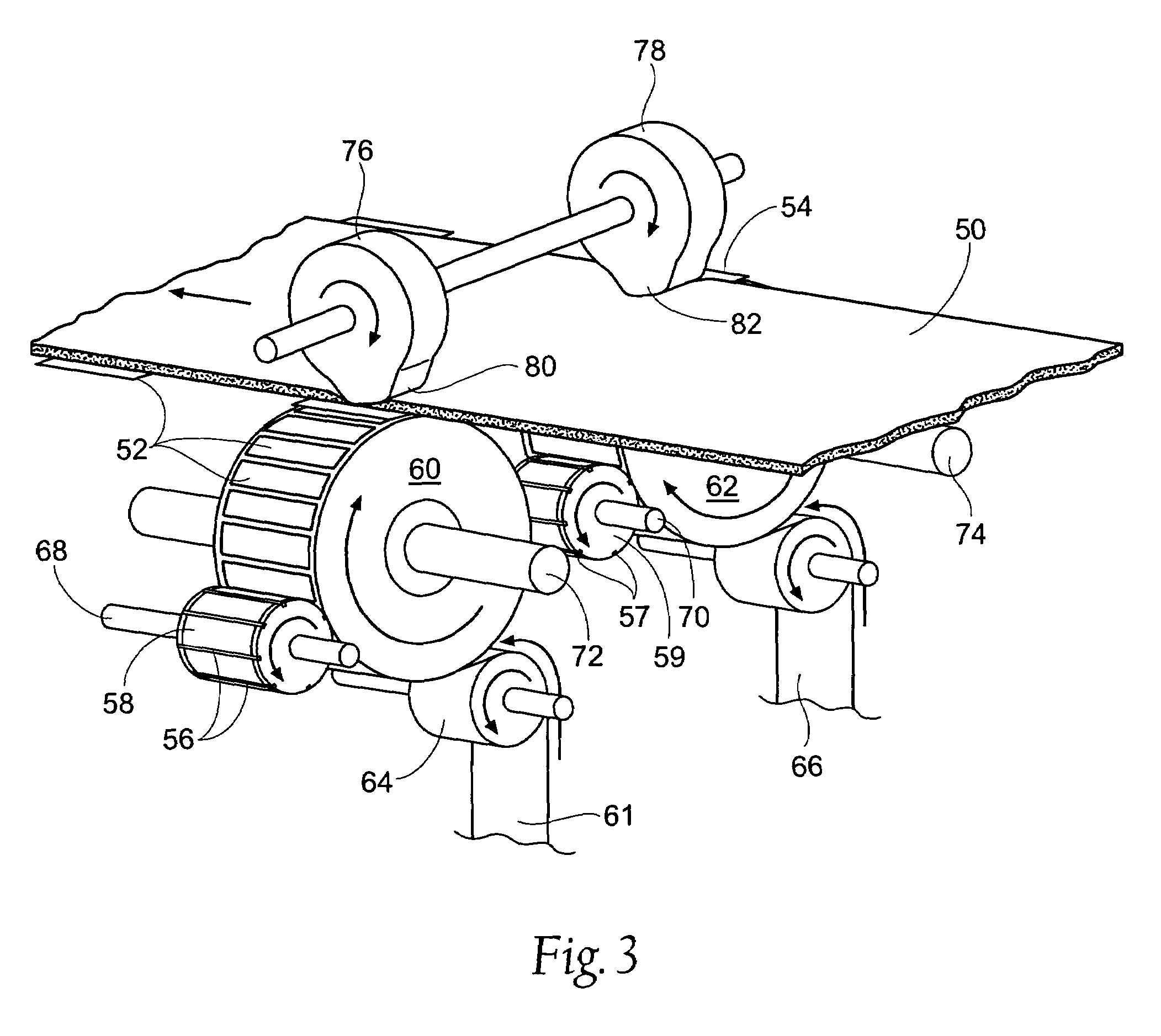
[0026]FIG. 2 is an overhead view of the improvement of the present invention. The tabs 12 are attached parallel to the moving web 10. The change in orientation is possible since an anvil that carries the adhesive tape 12 rotates i...


PUM

PropertyMeasurementUnit
adhesiveaaaaaaaaaa
lengthaaaaaaaaaa
axial stiffnessaaaaaaaaaa

Abstract

A method and apparatus for applying tape tabs to a traveling web of material when the tape tabs are moving at a non-parallel angle to the web of material. An anvil that carries the tape tabs moves at a perpendicular or other non-parallel angle to the web. The invention allows placement of the tape tabs at different arrangements, such as the tape tabs running parallel to the web of material. A wheel with a protuberance located near the web contacts the web to press the web down and adhere a tape tap to the moving web.

Description

RELATED APPLICATION[0001]This application claims the benefit of U.S. Provisional Patent Application Ser. No. 60 / 659,785, filed 9 Mar. 2005, and entitled “Transverse Tape Application Method and Apparatus.”BACKGROUND OF THE INVENTION[0002]The present invention relates to processes and apparatus for applying tabs to traveling webs, and more specifically to application of multiple tabs to a traveling web. The invention has particular applicability to the manufacture of disposable diapers.[0003]The history of cutting and applying tape tabs to disposable diaper webs is now entering its fourth decade. Over the course of that time, various types of automatic manufacturing equipment have been developed which produce the desired results with a variety of materials and configurations. This equipment generally included window-knife and slip-and-cut applicators, each having their own advantages and limitations.[0004]Window-knife applicators are comprised of: one or more rotating heads, each made...

Claims


Application Information

Patent Timeline
Patent Type & Authority Patents(United States)
IPC IPC(8): B29C65/50B29C65/56B32B37/22B44C1/24B65C9/30B32B37/26B65C9/20B44C1/17
CPCA61F13/15756B65H39/14B65H2801/57Y10T156/178Y10T156/1077Y10T156/1098Y10T156/133Y10T156/1089
Inventor ANDREWS, ROBERT E.
Owner CURT G JOA
Why Eureka
Try Eureka