Synchronized rear vision system

a rearview mirror and synchronization technology, applied in the field of vehicles, can solve problems such as not being recommended, and achieve the effects of eliminating cumbersome right-hand side rearview mirror adjustment effort, comfortable seating position, and eliminating re-adjustment effor

Active Publication Date: 2008-11-18
GM GLOBAL TECH OPERATIONS LLC
View PDF7 Cites 16 Cited by
  • Summary
  • Abstract
  • Description
  • Claims
  • Application Information

AI Technical Summary

Benefits of technology

[0015]One advantage of the present invention is that a synchronized rear vision system is provided for a vehicle that has an automatic setting detection and selection. Another advantage of the present invention is that the synchronized rear vision system enables a driver to use either the Blindzone setting method or the Blindzone / Glare Elimination (BGE) setting method to adjust the rear vision system. Yet another advantage of the present invention is that the synchronized rear vision system eliminates cumbersome right-hand side rearview mirror adjustment effort required by the BGE setting method. Still another advantage of the present invention is that the synchronized rear vision system reduces up to 70% of the worked for the driver in setting the rear vision system. A further advantage of the present invention is that the synchronized rear vision system eliminates re-adjustment effort when adjusting a driver seat of the vehicle. Yet a further advantage of the present invention is that the synchronized rear vision system allows personalized driver seat and rear vision system setting, providing a comfortable seating position for the driver, especially in the case of driving long distances. Still a further advantage of the present invention is that the synchronized rear vision system can enable a vehicle with lateral adjustment of the driver seat and / or with open cockpit (e.g. a drive-by-wire vehicle), providing comfortable and flexible seating position for the driver, thereby providing a better view of the front for the rear seat occupants.

Problems solved by technology

While the Blindzone method might be a more popular setting method, it is not a recommended method by experts unless the interior rearview mirror is obstructed, in which case, the method offers better coverage of the back of the vehicle.

Method used


Image

  • Synchronized rear vision system
  • Synchronized rear vision system
  • Synchronized rear vision system

Examples


Embodiment Construction

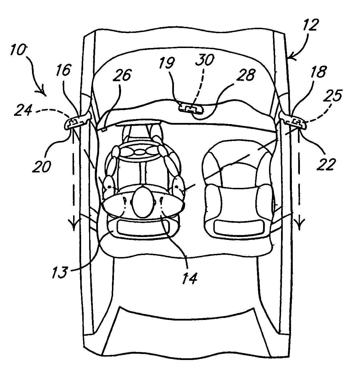
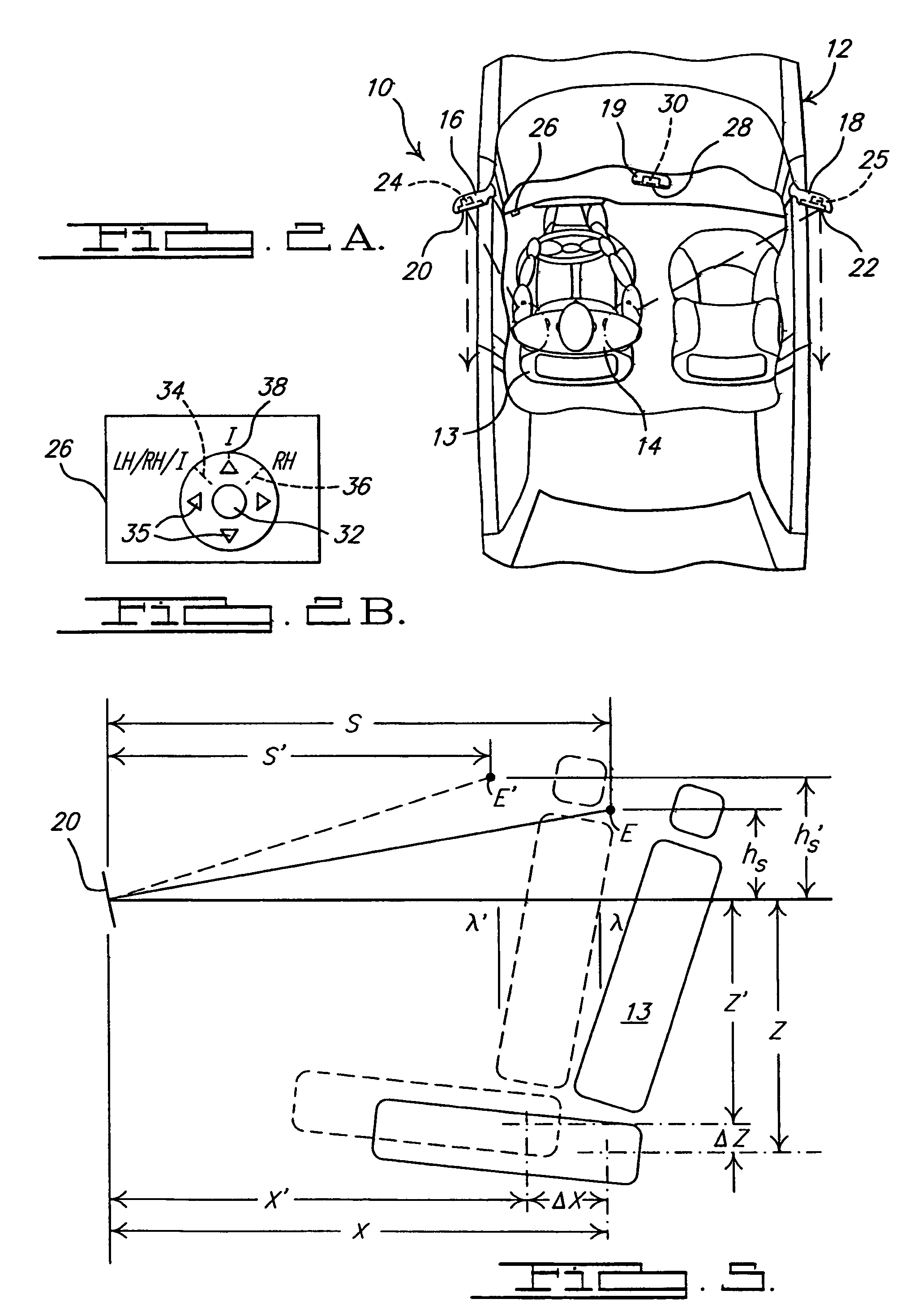
[0030]Referring to the drawings and in particular FIGS. 2A and 2B, one embodiment of a synchronized rear vision system 10, according to the present invention, is shown for a vehicle, generally indicated at 12. The vehicle 12 includes an adjustable driver seat 13 located in an occupant compartment of the vehicle 12. To assist an occupant driver 14 seated in the adjustable driver seat 13 in obtaining a view to a rear of the vehicle 12, the synchronized rear vision system 10 includes a left-hand, LH, side rearview mirror assembly 16, a right-hand, RH, side rearview mirror assembly 18, and an interior rearview mirror assembly 19. The side rearview mirror assemblies 16 and 18 are each disposed on a respective exterior side of the vehicle 12 and the interior rearview mirror assembly 19 is disposed in an interior or the occupant compartment of the vehicle 12.

[0031]Each side rearview mirror assembly 16 and 18 has a reflective element such as a mirror 20 and 22, respectively, having an angul...


PUM


Abstract

A synchronized rear vision system for a vehicle includes a pair of external side rearview mirrors for attachment to the vehicle and an interior rearview mirror for attachment to the vehicle. The synchronized rear vision system also includes a system master controller for detecting an instantaneous position of one of the side rearview mirrors and calculating position output signals for at least another one of the side rearview mirrors and the interior rearview mirror to automatically position at least the another one of the side rearview mirrors and the interior rearview mirror based on the instantaneous position. The synchronized rear vision system may include a controller to readjust the position of the rearview mirrors based on a position of a driver seat of the vehicle.

Description

CROSS-REFERENCE TO RELATED APPLICATION(S)[0001]The present application claims the benefit of U.S. Provisional Patent Application Ser. No. 60 / 645,225, filed Jan. 20, 2005.TECHNICAL FIELD[0002]The present invention relates generally to vehicles and, more particularly, to a synchronized rear vision system for a vehicle.BACKGROUND OF THE INVENTION[0003]It is known to provide a rear vision system for a vehicle such as a motor vehicle. Typically, the rear vision system includes a pair of outside or exterior side rearview mirrors, one on both driver and passenger sides of the vehicle, and an inside or interior rearview mirror in an occupant compartment of the vehicle.[0004]Such a rear vision system may be power operated to allow a driver to remotely and individually adjust the side and interior rearview mirrors without physically attending them. These mirrors are typically adjustable both vertically (up / down) and horizontally (left / right), using electric motors controlled by the driver via...

Claims


Application Information

Patent Timeline
Patent Type & Authority Patents(United States)
IPC IPC(8): G05B11/01
CPCB60R1/025
Inventor WANG, JENNE-TAISALA, DOREL M.PARYANI, KIOUMARS
Owner GM GLOBAL TECH OPERATIONS LLC
Why Eureka
Try Eureka