Magnetic MEMS sensor device

a sensor device and magnetofloat technology, applied in the field of magnetic devices, can solve the problems of inaccurate measurement, limited use of piezoelectric devices as sensors, and inability to accurately model springs, etc., and achieve the effect of accurate measurement of motion

Inactive Publication Date: 2008-11-18
SAMSUNG ELECTRONICS CO LTD
View PDF12 Cites 20 Cited by
  • Summary
  • Abstract
  • Description
  • Claims
  • Application Information

AI Technical Summary

Benefits of technology

[0006]To solve the problems above, the present invention is conceived. A novel microelectromechanical system (MEMS) sensor for accurate measurement of motions, forces or displacement is provided.

Problems solved by technology

The use of piezoelectric devices as sensors, however, is limited due to their sensitivity to variations in temperature.
Such accelerometers, however, require complicated designs to fabricate and it is often difficult to accurately model the spring constant of the MEMS-scale spring, allowing for the possibility of inaccurate measurements.

Method used


Image

  • Magnetic MEMS sensor device
  • Magnetic MEMS sensor device
  • Magnetic MEMS sensor device

Examples


Embodiment Construction

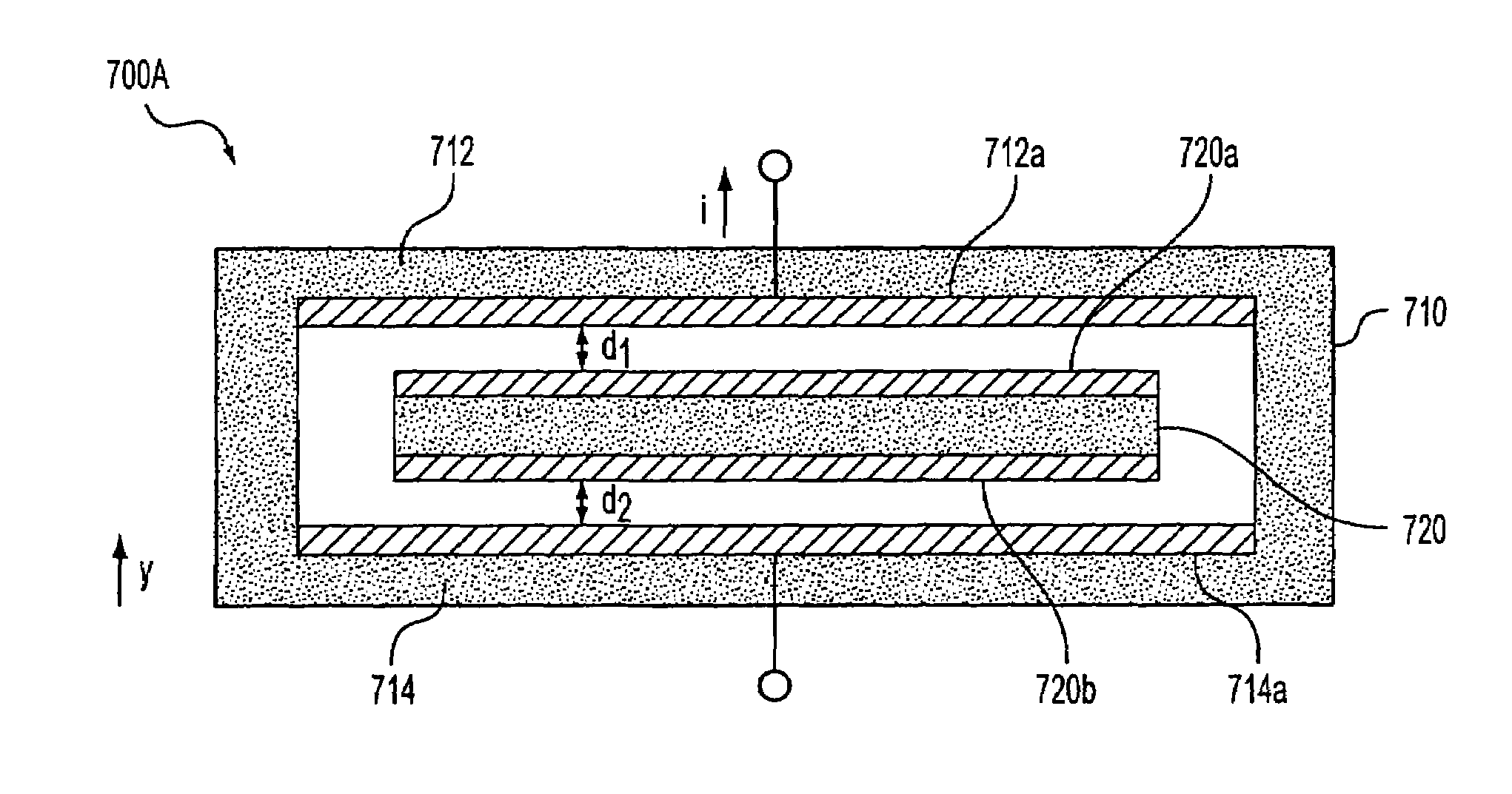
[0029]An apparatus according to one aspect of the present invention includes an outer member formed from a wafer such as a Si wafer and an inner member fabricated inside the outer member. A magnetic material is laminated onto the outer and inner members so that repulsive magnetic forces magnetically levitate the inner member.

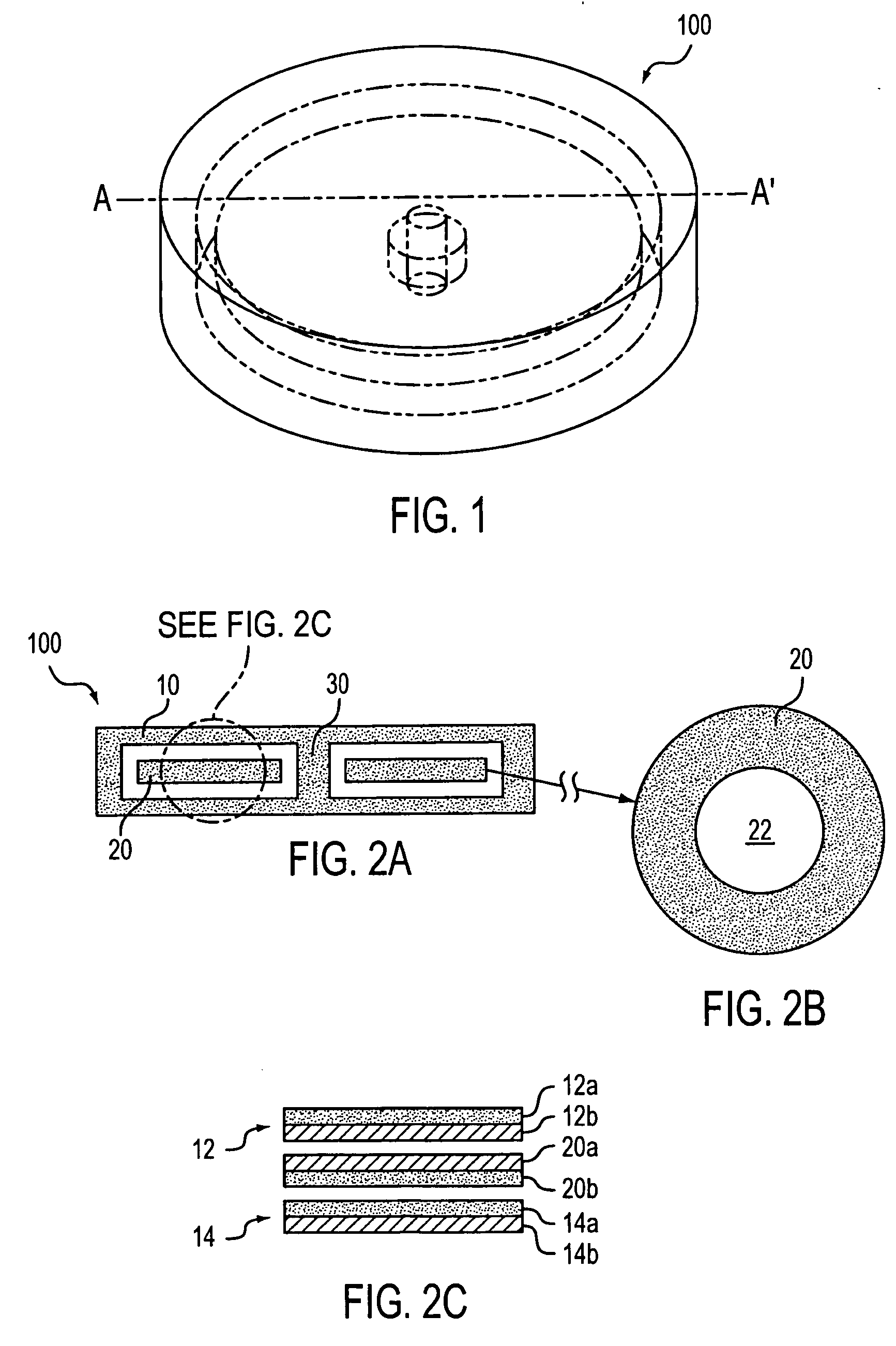
[0030]In FIGS. 1 and 2A-C, an exemplary embodiment of the present invention is shown. The magnetic sensor device 100 includes an outer member 10 and an inner member 20. The outer member 10 includes an upper member 12 and a lower member 14. The inner member 20 is disk-shaped with a center hole 22, as shown in the cross sectional view A-A′ of the inner member 20 (FIG. 2B). The inner member 20 is disposed between the upper and the lower members 12, 14. A spindle 30 is disposed inside the outer member 10 and passes through the center hole 22 of the inner member 20. The outer and the inner members 10, 20 each has magnetic properties arising from the magnetic material...


PUM

PropertyMeasurementUnit
magneticaaaaaaaaaa
forcesaaaaaaaaaa
conductiveaaaaaaaaaa

Abstract

A microelectromechanical system (MEMS) sensor and method for measuring the motion of an intermediate member and a method for making the MEMS sensor. The MEMS sensor includes a substrate, a lower magnetic member disposed on the substrate, a layer disposed over the substrate, an upper magnetic member disposed at a side of the layer facing the lower magnetic member, an intermediate magnetic member magnetically levitated between the lower magnetic member and upper magnetic member; and a component measuring at least one of motion, forces acting on, and a displacement of the intermediate magnetic member.

Description

BACKGROUND OF THE INVENTION[0001]1. Field of the Invention[0002]Apparatuses and methods consistent with the present invention relate to magnetic devices fabricated using microelectromechanical system (MEMS) process. Specifically, the apparatuses and methods relate to MEMS magneto-floating sensors, a method for fabricating a MEMS magneto-floating sensor, and a method of using a MEMS magneto-floating sensor to detect displacement, motion and force.[0003]2. Description of the Related Art[0004]Advances in micromachining technology have advanced the development of miniature MEMS sensors. An example of a MEMS sensor is a piezoelectric sensor which is used in a variety of applications, ranging from pressure sensors to accelerometers for automobile airbags. The use of piezoelectric devices as sensors, however, is limited due to their sensitivity to variations in temperature.[0005]Another example of a MEMS sensor is a mass-spring system accelerometer. Such accelerometers, however, require co...

Claims


Application Information

Patent Timeline
Patent Type & Authority Patents(United States)
IPC IPC(8): G01R27/26G01P3/44B81B3/00B81B5/00B81B7/02F16C39/06G01B7/00G01B7/30G01C5/00G01C19/06G01C19/16G01C19/42G01C19/56G01D5/245G01D11/02G01L1/12G01P3/486G01P3/488G01P15/08G01P15/125G01V7/00H02N15/00
CPCB81B3/0021G01P3/486G01P3/488G01P15/08G01P15/0802G01P15/125B81B2201/0235B81B2201/0264B81B2201/0292B81B7/02
Inventor WON, JONG-HWACHOI, HYUNGKIM, KWON-HEEKWON, OH-MYOUNG
Owner SAMSUNG ELECTRONICS CO LTD
Why Eureka
Try Eureka