Jig apparatus

a jig and jig technology, applied in the field of jigs, can solve the problems of difficult to understand how adjustments affect the finished workpiece, poor fitting joints may detract from the overall project aesthetics and functionality, and the jigs are complex to set-up for use, so as to achieve the effect of increasing versatility

Inactive Publication Date: 2008-11-25
BLACK & DECKER INC
View PDF229 Cites 21 Cited by
  • Summary
  • Abstract
  • Description
  • Claims
  • Application Information

AI Technical Summary

Benefits of technology

[0012]In an additional aspect of the invention, a template mounting system is discussed. In embodiments, suitable template mounting systems include opposing slotted brackets, included on a template, received by a threaded lock-down knob system. In further embodiments, a mounting bracket includes an elongate rail for receiving a template including an aperture or channel corresponding to the rail. A template mounting system in accordance with the present aspect may permit the utilization of a single template having multiple guides so as to provide increased versatility. The mounting system may allow for adjustable positioning with respect to a jig base having a first side and a second side orthogonally aligned to each other.
[0013]In a further aspect of the present invention, a visual alignment system may be included in the jig apparatus for assisting the user in proper alignment of the template with the workpiece / the base. In embodiments, a visual indicia or marker such as a scribed line may be included on a template, to be implemented with the jig apparatus, for providing a visual alignment for an edge of the workpiece / the abutment of workpieces to be shaped.
[0016]In an additional aspect of the present invention, a router bit positioning system is described. The router bit positioning system may promote efficient positioning of the depth of a router bit, or the extent to which a router bit extends beyond a router base / sub-base. A bit stop may be mounted to the base, an extension included on the template, or a dedicated housing in-line with a slot or recess included in a support surface (e.g., a template). The bit stop may be fixed at a pre-selected depth commonly implemented to offset distance or allow for adjustment such as by utilizing a threaded rod, screw or the like.

Problems solved by technology

Poorly fitting joints may detract from the overall projects aesthetics and functionality, especially for fine cabinetry.
Too often these jigs tend to be complex to set-up for use, difficult to understand how adjustments impact the finished workpiece, and lack efficient methods for reestablishing commonly made joinery, such as dovetails, box joints, and mortise and tenon joints.
Expert woodworkers, in contrast, may become frustrated with the set-up time required for the jig device.
Typical jig devices may lack the ability to form a wide variety of joints.
In addition to the expense, these devices may consume valuable workshop space.
While some devices permit the formation of various types of joinery such as through dovetails, half-blind dovetails of various fixed spacings, and box joints, a user may tend to accept a lesser quality joint due to set-up errors, or be required to conduct test cuts to ensure the desired fit is obtained.
Correspondingly, if the cutting bit extends too far into the workpiece the joint may be too tight.
Other jig alignment issues may also affect the overall fit and finish of the resultant workpiece.
For instance, improper alignment of an end of a workpiece with respect to a template may result in a joint which is either loose or too tight.
In additional instances, some existing jigs fail to offer convenient workpiece positioning and securing.
Difficulties with some securing devices include the inability of the securing device to effectuate both coarse and fine adjustment in a convenient manner.
For example, some securing devices may be difficult for the user to secure while properly positioning the workpiece.
Typically, such non-standard joints are only attempted by experienced woodworkers who demand devices having full features.
In addition to the difficulties experienced in setting-up the jig, dust and debris generated by operation of a hand-held router removing material, from the workpiece during shaping operations, may be problematic to remove or tend to get caught between the router sub-base plate and the fingers / template.
This may slow overall progress and become an annoyance to the woodworker.

Method used


Image

  • Jig apparatus
  • Jig apparatus
  • Jig apparatus

Examples


Embodiment Construction

[0051]Reference will now be made in detail to the presently preferred embodiments of the invention, examples of which are illustrated in the accompanying drawings. It is to be appreciated that generally corresponding structures are provided with corresponding reference numbers. Additionally, while the present embodiments are directed generally to an apparatus in which a hand-held router is manipulated with respect to a fixed workpiece, the principles of the present invention may be equally applicable to an apparatus which is implemented with a fixed cutter such as in a router table, and the like devices for woodworking. It is the intention of this disclosure to encompass and include such variation.

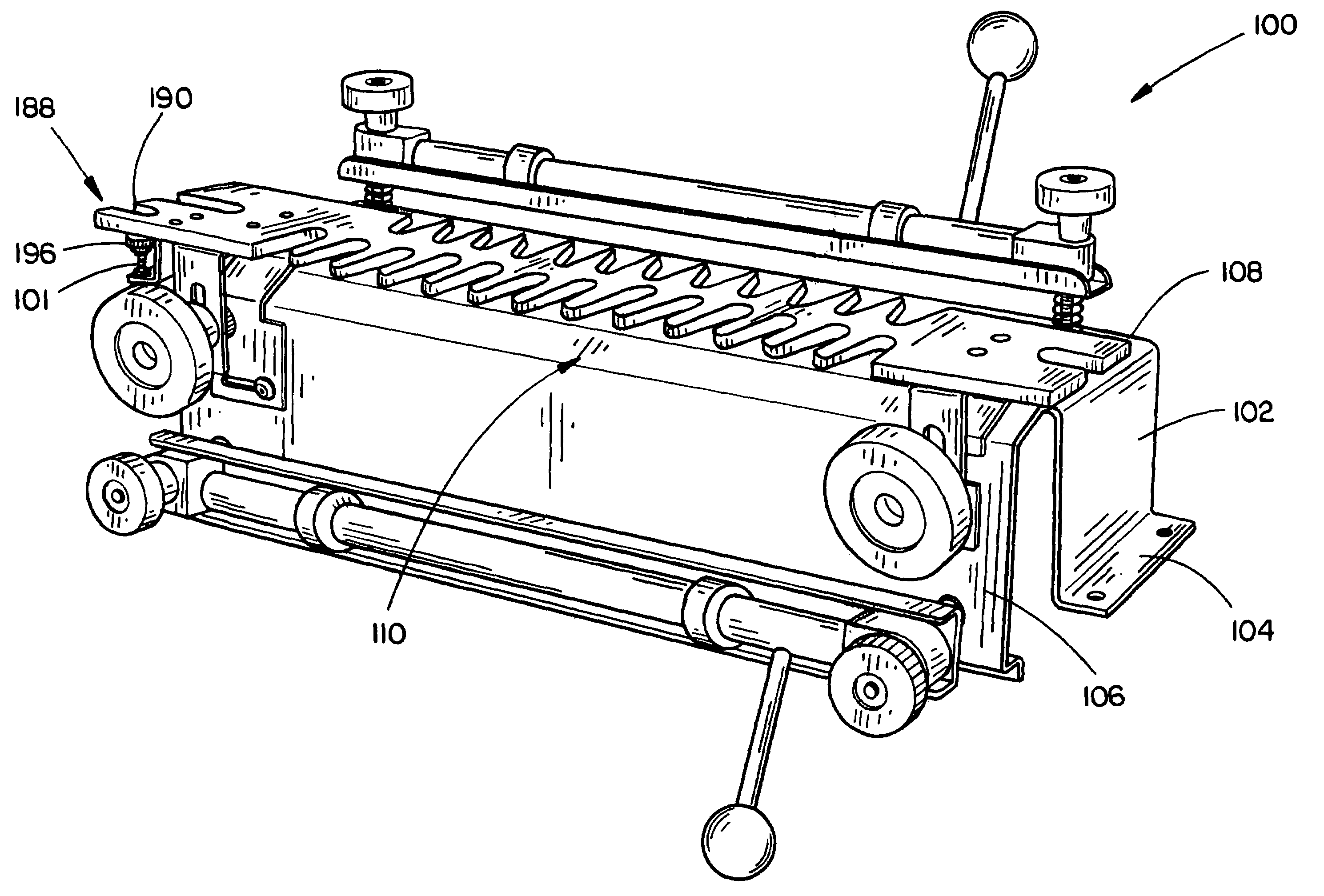
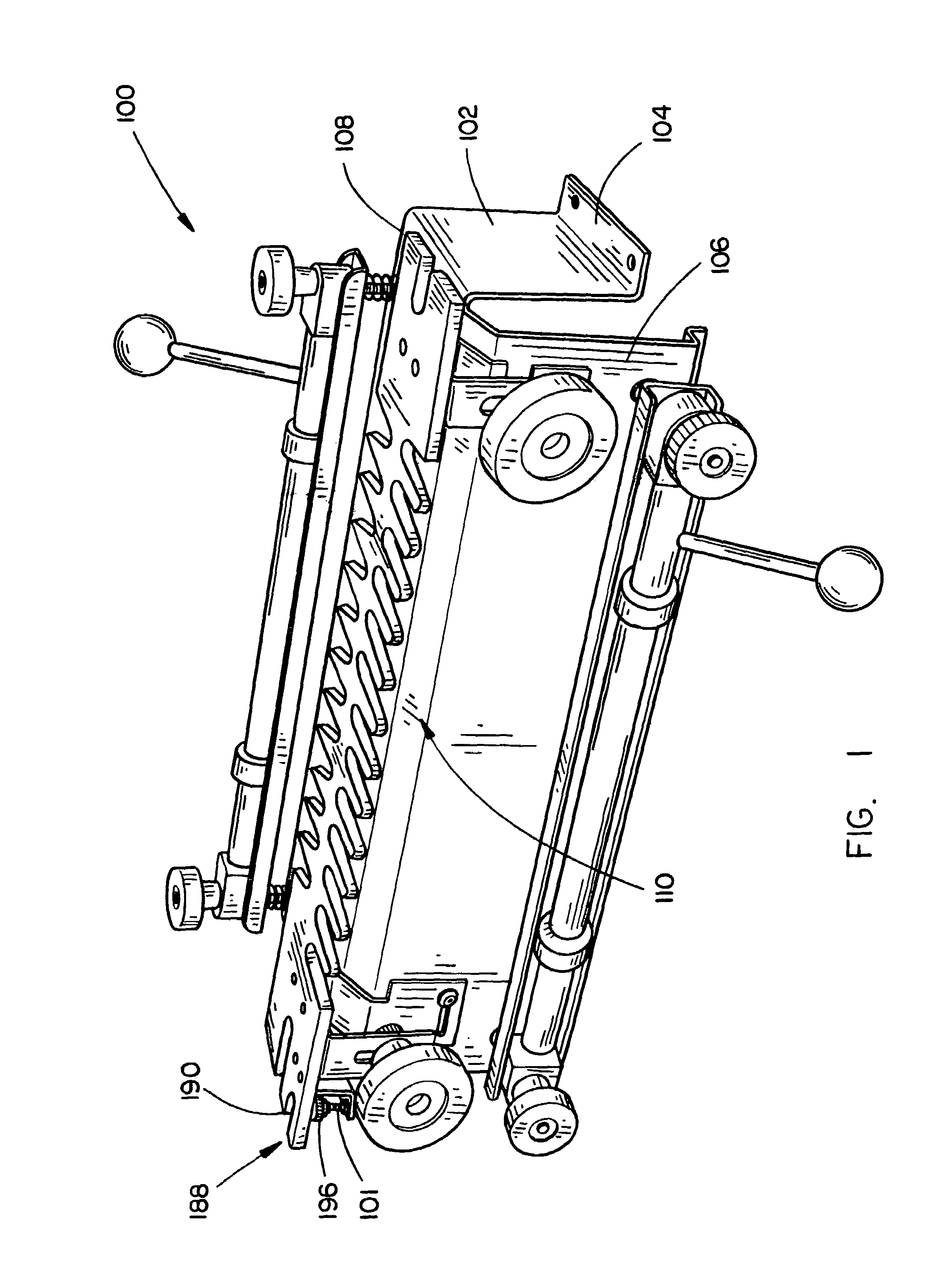
[0052]Referring to FIG. 1, in the present embodiment of the invention, a jig apparatus 100 is discussed. The present apparatus 100 may be implemented to assist in forming a wide variety of joinery connections in an efficient manner.

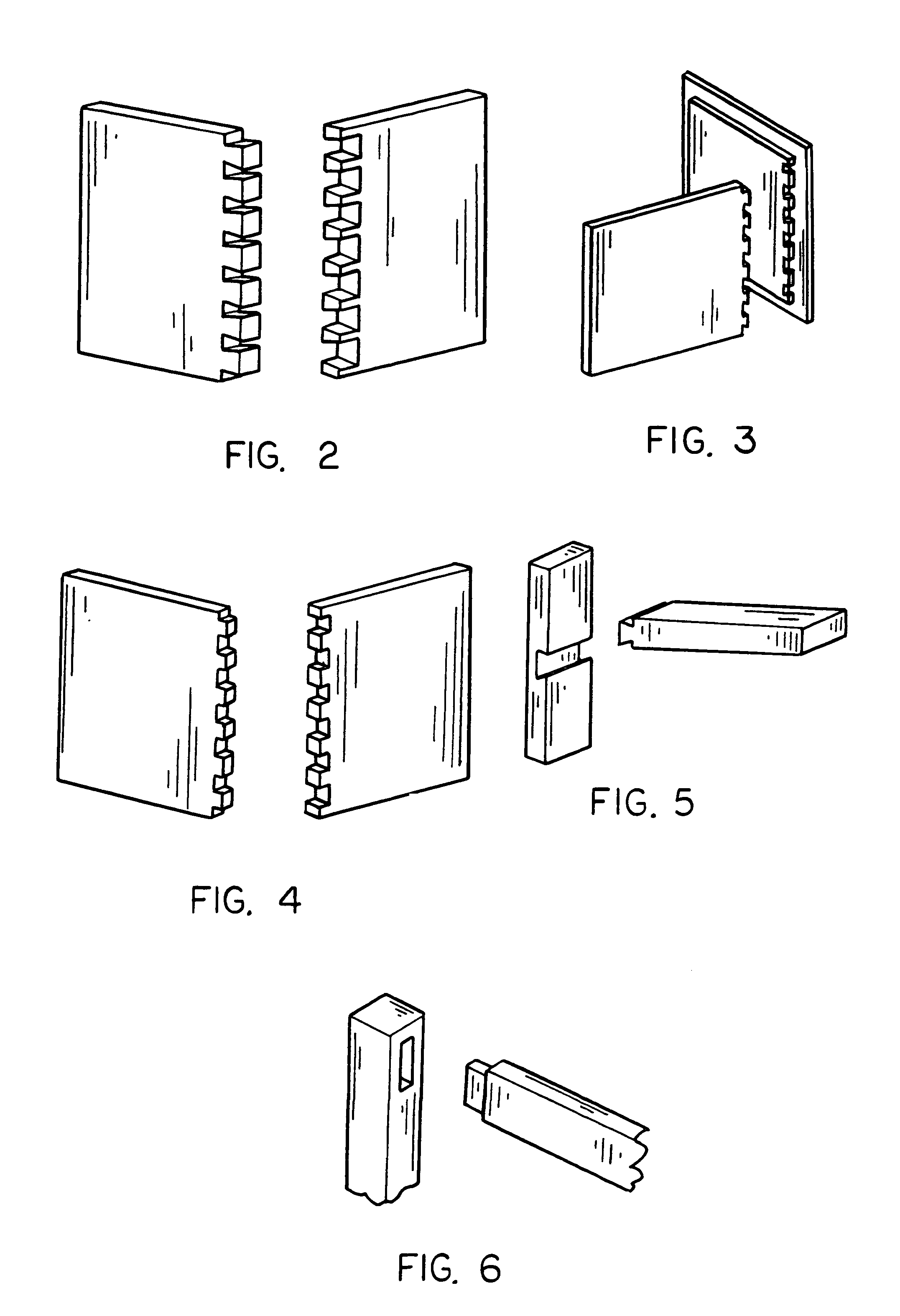
[0053]Referring to FIGS. 2 through 6, while not inclusive,...


PUM

PropertyMeasurementUnit
angleaaaaaaaaaa
structuresaaaaaaaaaa
timeaaaaaaaaaa

Abstract

A jig apparatus for aiding in the formation of a variety of mechanically interconnecting structures in workpieces. The jig apparatus may include a base and a template mounting system for adjustably positioning a template with respect to the base. A securing system for securing a workpiece in a desired position may be included. An adjustable workpiece mounting fence may also be included for varying the angular orientation of a workpiece to be shaped with respect to a template. Additionally, a collar guide system for a router for utilization with a template may be implemented with a hand held router being implemented for removing material from a workpiece. A router bit positioning system for aiding in establishing a pre-determined bit depth may be included.

Description

CROSS REFERENCE[0001]The present application claims priority under 35 U.S.C. §119(e) to U.S. Provisional Patent Application Ser. No. 60 / 592,734, entitled: Jig Apparatus, filed on Jul. 30, 2004, and to U.S. Provisional Patent Application Ser. No. 60 / 664,053, entitled: Jig Apparatus, filed on Mar. 22, 2005, both of which are hereby incorporated by reference in their entirety.FIELD OF THE INVENTION[0002]The present invention generally relates to the field of woodworking and more particularly to joinery.BACKGROUND OF THE INVENTION[0003]The ability of a craftsperson to form fine joinery such as cabinetry is often the true measure of the person's woodworking skill. Poorly fitting joints may detract from the overall projects aesthetics and functionality, especially for fine cabinetry. Proper fit and assembly often require a high level of skill or a large time commitment on behalf of a novice woodworker. To aid in the process, a woodworker will often employ a jig or form to assist in proper...

Claims


Application Information

Patent Timeline
Patent Type & Authority Patents(United States)
IPC IPC(8): B27C5/00
CPCB27C5/10B27F1/12Y10T409/303696
Inventor MCDANIEL, STEVEN D.BEHNE, ROCKNE W.WILLARD, MATTHEW C.
Owner BLACK & DECKER INC
Why Eureka
Try Eureka