
Anti-fog dental mirror

a dental mirror and anti-fog technology, applied in the field of dental mirrors, can solve the problems of short-lived events, mirrors tend to “fog up”, and thin film of solution left on the mirror surface, and achieve the effect of quick and easy cleaning

Inactive Publication Date: 2008-11-25
BARSTOW RICKY A
View PDF4 Cites 12 Cited by
  • Summary
  • Abstract
  • Description
  • Claims
  • Application Information

AI Technical Summary

Benefits of technology

[0006]It is an object of the present invention to provide a dental mirror which may be quickly and easily cleaned.
[0007]It is another object of the present invention to provide a dental mirror which easily applies a coating of anti-fog solution on the mirror surface.
[0009]In general, a dental mirror includes a mirror assembly, a handle having an interior cavity and a non-circular aperture proximate one end, the aperture communicating with the interior cavity, a push-arm extending through the aperture toward the mirror assembly, the push-arm having a non-circular shape, the push-arm also having a wiper support, and a wiper secured within the wiper support, wherein the push-arm is selectively movable to move the wiper over the mirror assembly, the aperture preventing relative rotation of the push-arm.

Problems solved by technology

At room temperature dental mirrors tend to “fog up” when placed inside a patient's warm, humid mouth.
This event, however, is sometimes short lived because the moment the dentist, hygienist, or dental assistant uses a hand-piece drill, or air and water syringe, the thin film of solution left on the mirror surface is disrupted.
Consequently, during most routine dental procedures, the thin clear film of anti-fog solution on the dental mirror surface is disrupted and splattered with debris.
Once the mirror surface is disrupted, it is useless to visualize the operative site.
Such a procedure is time consuming and inefficient and often times the mirror is splattered again within seconds.
Some patients can not tolerate oral fluids accumulating within their oral cavity because their soft palate does not seal well against their tongue to prevent fluids from making their way into the throat.
This naturally causes coughing and / or a gag reflex that interferes with the patient's comfort.
Further, the coughing and gag movement make procedures more difficult for the dentist.
In addition, many dental procedures require a dry field since they involve adhesive bonding.
In those cases, the water spraying procedure to clear the dental mirror is not an option.

Method used


Image

  • Anti-fog dental mirror
  • Anti-fog dental mirror
  • Anti-fog dental mirror

Examples


Embodiment Construction

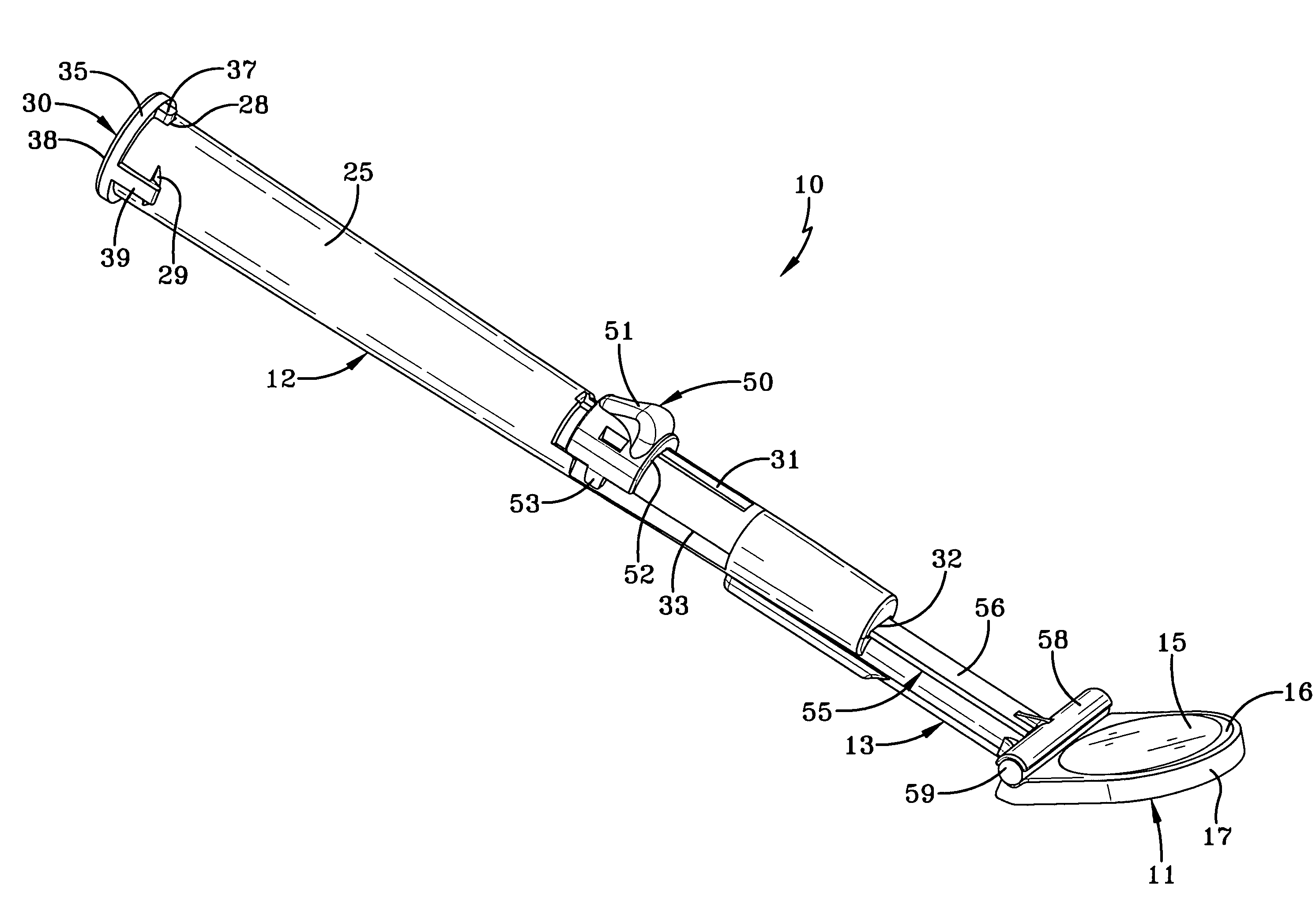
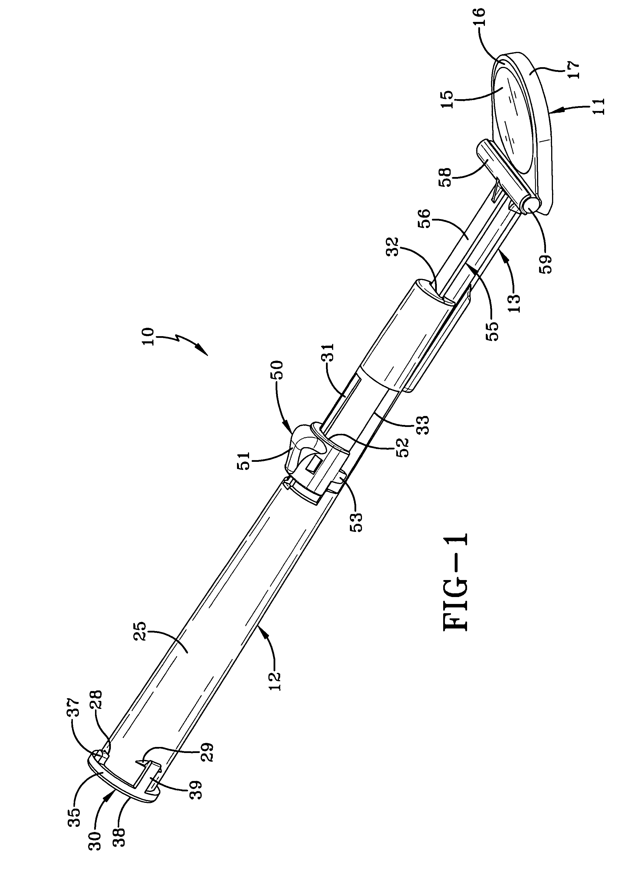
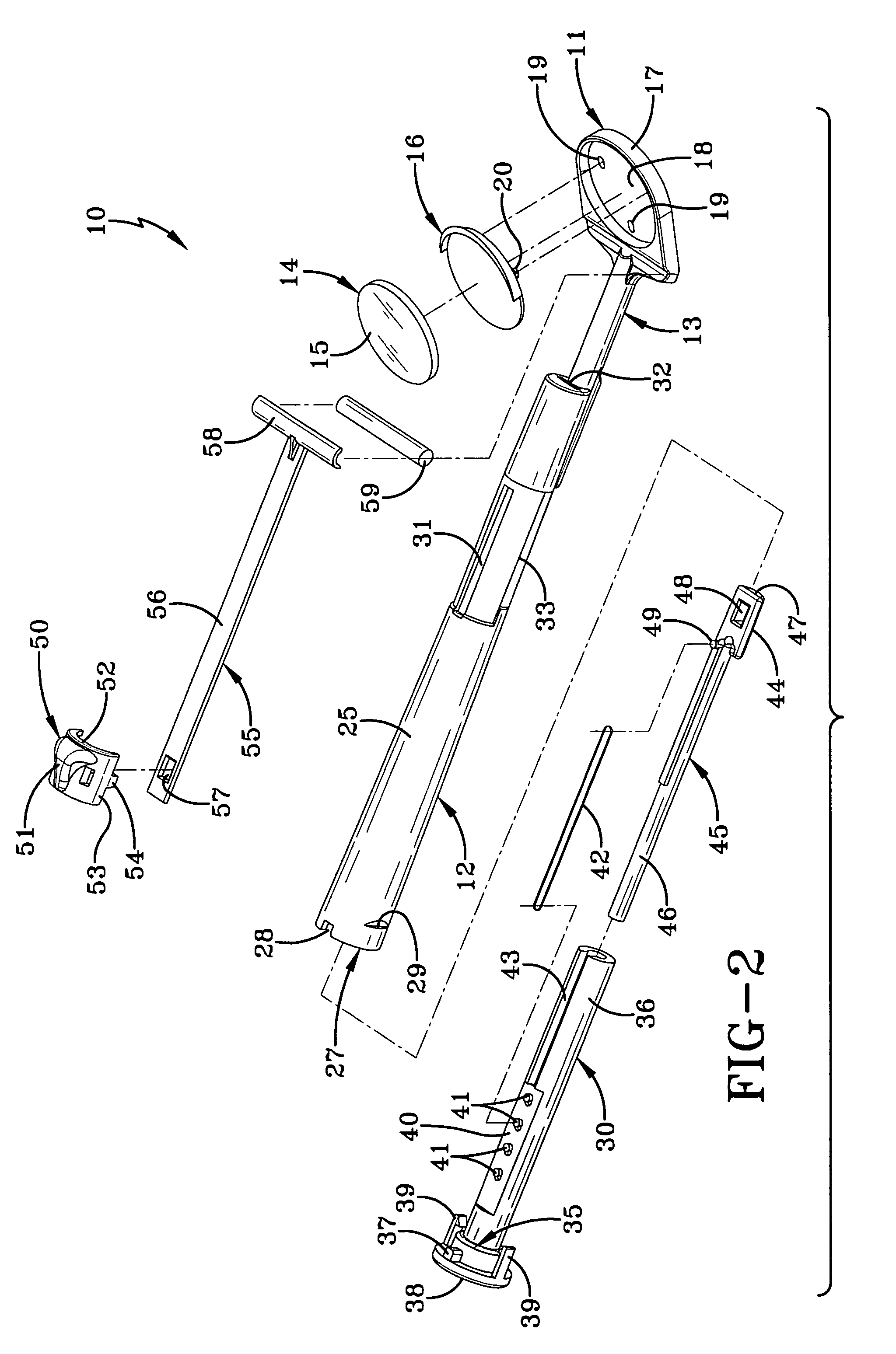
[0020]Referring now to FIG. 1, a dental mirror, generally indicated by the numeral 10, includes a mirror assembly generally indicated by the numeral 11. Mirror assembly 11 is attached to a handle 12 via a stem 13 and is disposed at an angle α relative to stem 13 to provide promote visibility within an oral cavity. In a particularly preferred embodiment, angle α may be from about 15 to 20 degrees. However, it should be appreciated that mirror assembly 11 may be disposed at any angle α, depending upon the application or procedure.

[0021]Referring to FIGS. 1-4, mirror assembly 11 includes a mirror 14 which has a reflective surface 15 adapted to reflect light and provide visibility within the oral cavity. The mirror 14 is secured to a housing 16 via any means known in the art. For example, mirror 14 may be secured using adhesive or mechanical attachment means. Mirror assembly 11 also includes a head portion 17 that is secured to stem 13. Stem 13 and head portion 17 may be a unitary membe...


PUM


Abstract

A dental mirror includes a mirror assembly and a handle having an interior cavity. The handle further includes a non-circular aperture proximate one end, which communicates with the interior cavity. A push-arm extends through the aperture toward the mirror assembly and has a non-circular shape. The push-arm also has a wiper support, and a sponge is secured within the wiper support. The push-arm is selectively movable to carry the sponge over the mirror assembly, and the aperture prevents relative rotation of the push-arm.

Description

TECHNICAL FIELD[0001]The present invention relates generally to a dental mirror, and more particularly to a dental mirror including a retractable wiper sponge which deposits anti-fog solutions on the mirror.BACKGROUND ART[0002]At room temperature dental mirrors tend to “fog up” when placed inside a patient's warm, humid mouth. Prior methods of preventing mirror fog up included dipping the mirror into a mirror de-fogging solution before insertion into the mouth. The thin film of solution left on the mirror's glass surface thereafter improved visibility for the operator. This event, however, is sometimes short lived because the moment the dentist, hygienist, or dental assistant uses a hand-piece drill, or air and water syringe, the thin film of solution left on the mirror surface is disrupted. The aforementioned high speed dental hand-pieces spray water to cool and flush tooth debris from the operative site. Also, air and water syringes are used to flush and aid in clearing the debris...

Claims


Application Information

Patent Timeline
Patent Type & Authority Patents(United States)
IPC IPC(8): A61B1/24A61B1/00A61B1/267A61C1/00A61C9/00
CPCA61B1/126A61B1/127A61B1/253B08B1/008B08B1/30
Inventor BARSTOW, RICKY A.
Owner BARSTOW RICKY A
Learn More