Sub signal modulation apparatus, sub signal demodulation apparatus, and sub signal modulation demodulation system

sub signal technology, applied in the field of sub signal modulation demodulation system, sub signal modulation apparatus, can solve the problems of difficult to apply the technique of the patent reference 1 to a normal msa transceiver without a sub signal modulation function, difficult to stably transmit sub signal,

Inactive Publication Date: 2008-11-25
FUJITSU LTD
View PDF15 Cites 4 Cited by
  • Summary
  • Abstract
  • Description
  • Claims
  • Application Information

AI Technical Summary

Benefits of technology

[0027]Since the stabilizing controller of the present invention can control the attenuation determining section such that an amplitude of the attenuation of the variable optical attenuator is stabilized to have a constant ratio to a mean intensity of the main signal light, it is possible to stabilize, irrespective of the intensity of main signal light, transmission of a sub signal superimposed on the main signal light even when a general-purpose main signal light transmitter is used.

Problems solved by technology

For this reason, it is difficult to apply the technique of the patent reference 1 to a normal MSA transceiver without a sub signal modulation function.
Besides, partly since of the patent reference 2 does not have a configuration for stabilizing the amplitude of a sub signal and partly since, if the level of a light data signal to be receive varies, a relative level of the amplitude of the sub signal to an intensity of the light data signal also varies, it is difficult to stably transmit the sub signal.
The patent references 3-6 do not disclose techniques able to solve the above problem that a sub signal cannot be stably transmitted which problem is caused by a variation in relative level of the amplitude of the sub signal to the intensity of main signal light serving as light data signal.

Method used


Image

  • Sub signal modulation apparatus, sub signal demodulation apparatus, and sub signal modulation demodulation system
  • Sub signal modulation apparatus, sub signal demodulation apparatus, and sub signal modulation demodulation system
  • Sub signal modulation apparatus, sub signal demodulation apparatus, and sub signal modulation demodulation system

Examples


first embodiment

(A) First Embodiment

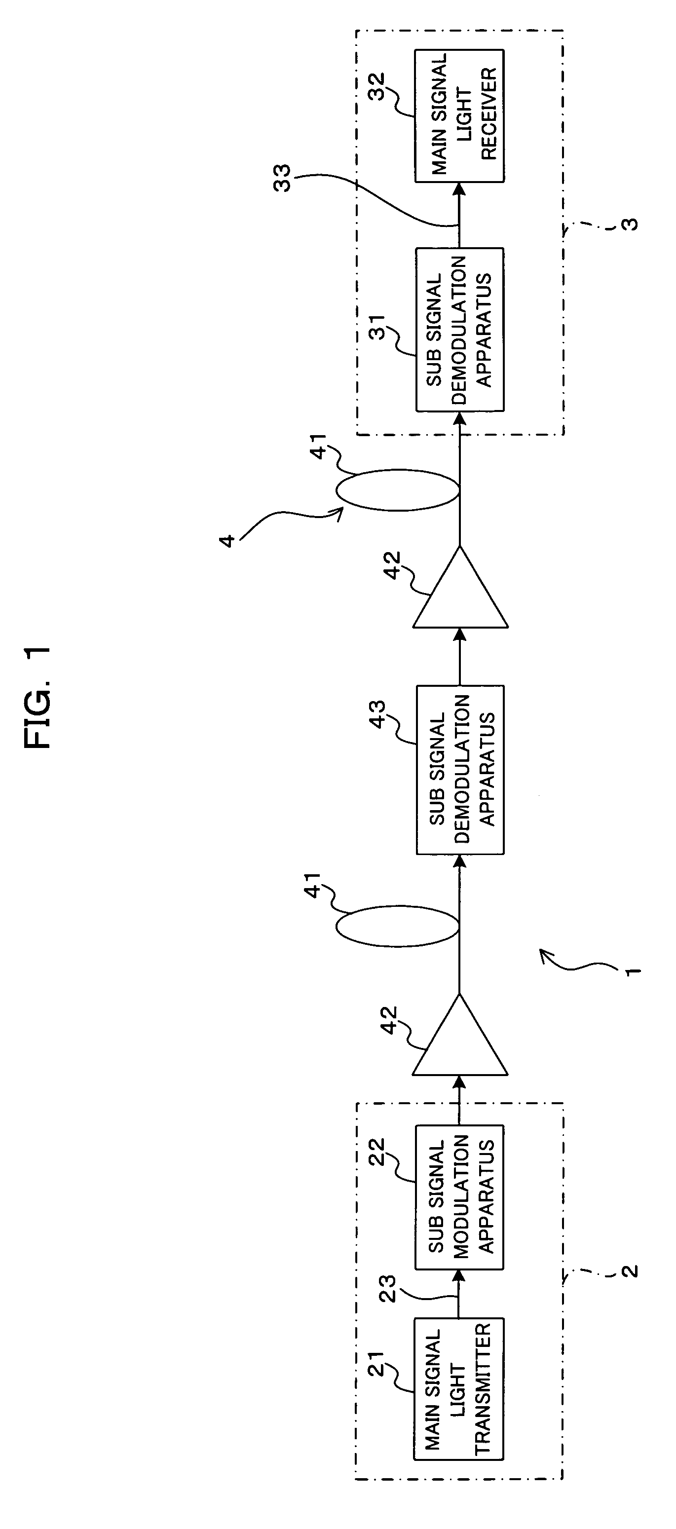
[0036]FIG. 1 schematically shows an optical communication system 1 according to a first embodiment of the present invention. In the optical communication system 1 shown in FIG. 1, a transmitter station 2 and a receiver station 3 are connected by an optical transmission path 4, which includes optical fibers 41 and an optical amplifier 42 interposed between the optical fibers 41 and which transmits light signals from the transmitter station 2 to the receiver station 3.

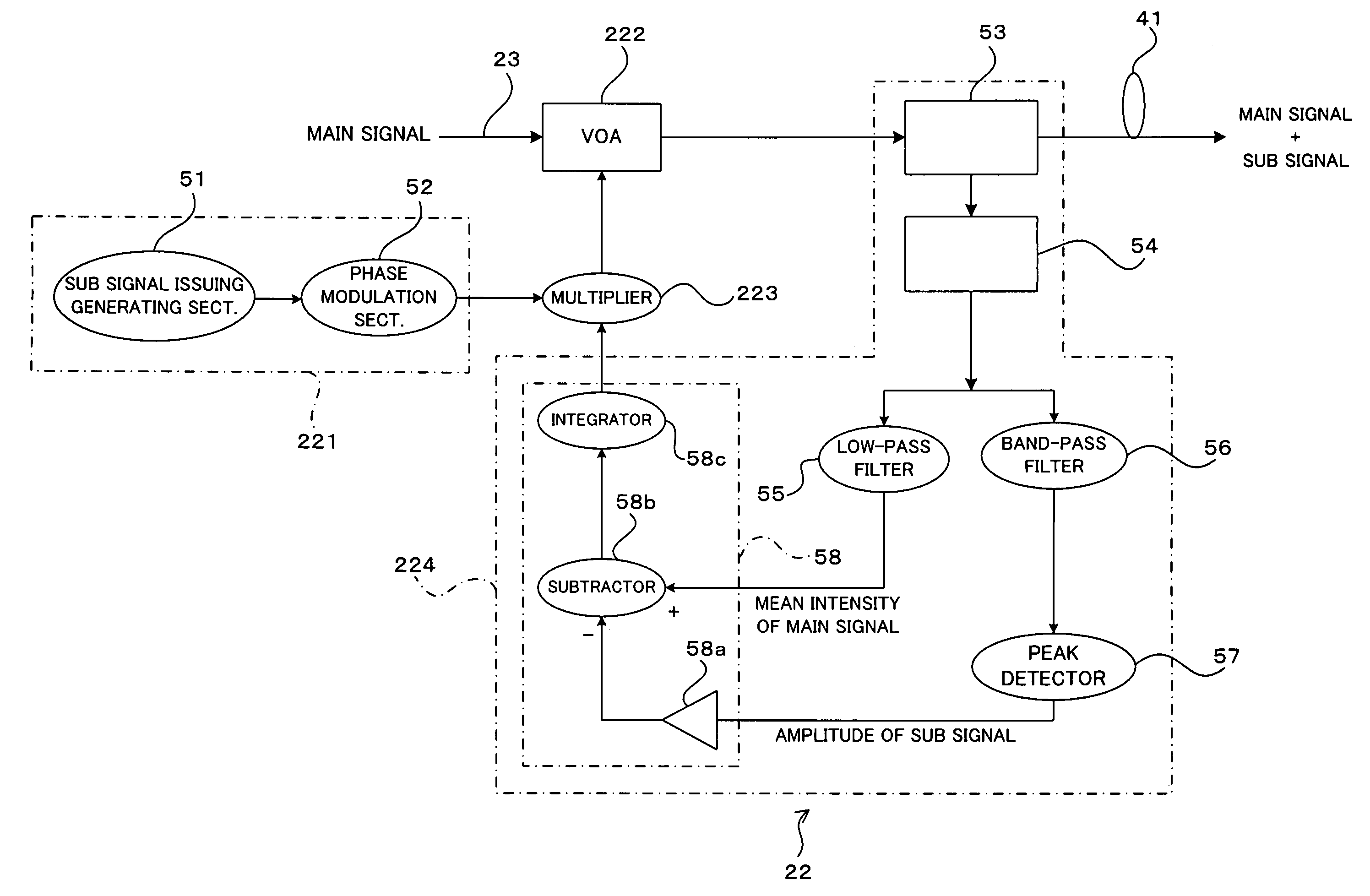
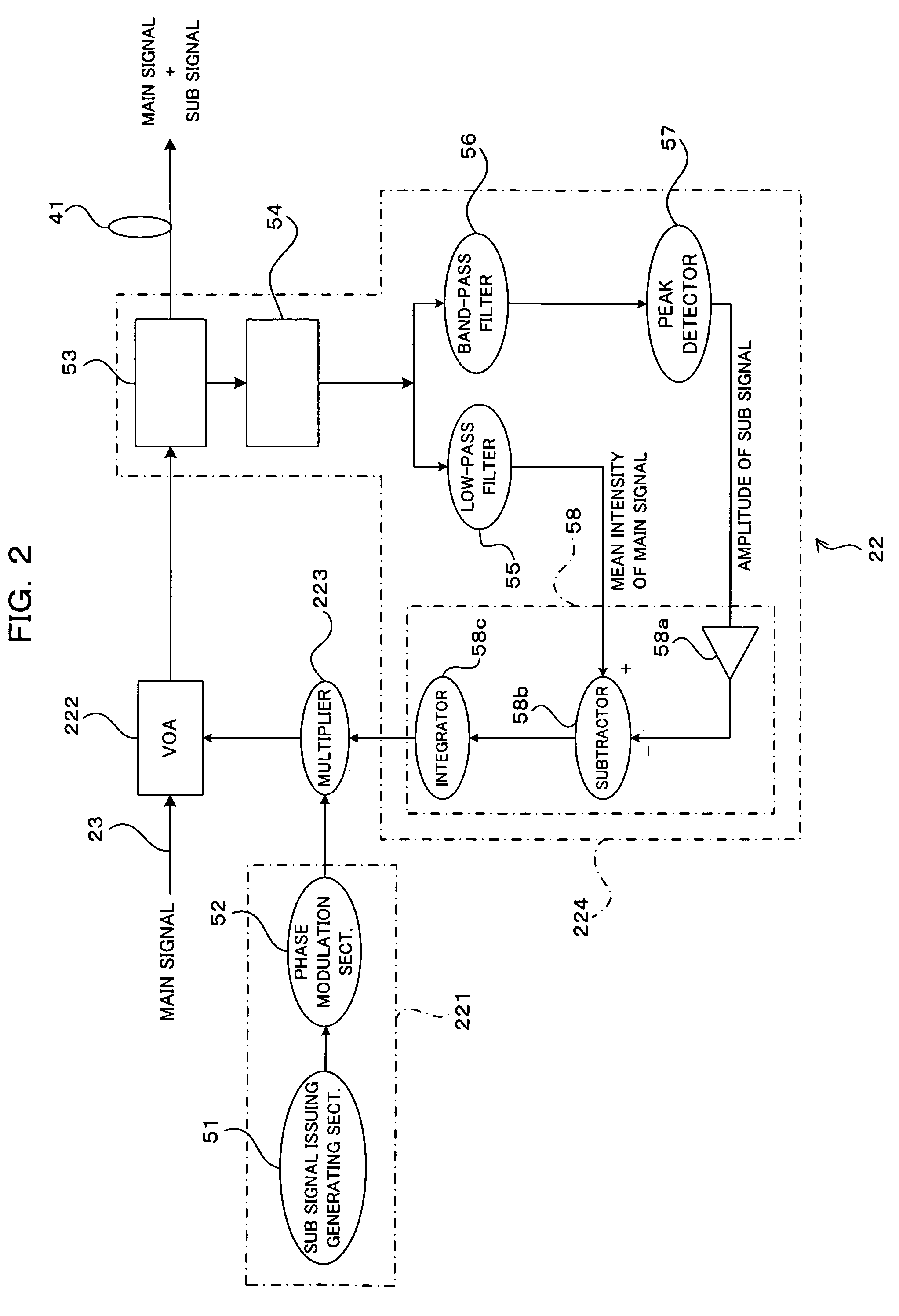
[0037]The transmitter station 2 includes a main signal light transmitter 21 for outputting main signal light to be transmitted to a receiver station 3 and a sub signal modulation apparatus 22 for modulating the main signal light from the main signal light transmitter 21 by a sub signal and transmitting the modulated main signal to the receiver station 3. By way of an example, a general-purpose MSA transceiver can be used as the main signal light transmitter 21.

[0038]Here, a sub signal is different fro...


PUM


Abstract

A sub signal modulation apparatus, with the intention of stabilized transmission of a sub signal superimposed on main signal light irrespective of the intensity of the main signal light when used in a general-purpose main signal transmitter, including a sub signal outputting unit; a variable optical attenuator for variably attenuating main signal light, into which the main signal has been modulated, at a response speed lower than ½ of a speed of the main signal; an attenuation determining unit for determining, in accordance with the sub signal output from the sub signal outputting unit, an attenuation of the variable optical attenuator for the main signal light; and a stabilizing controller for controlling the attenuation determining unit such that an amplitude of the attenuation of the variable optical attenuator is stabilized to have a constant ratio to a mean intensity of the main signal light.

Description

BACKGROUND OF THE INVENTION[0001]1. Field of the Invention[0002]The present invention relates to a sub signal modulation apparatus, a sub signal demodulation apparatus and a sub signal modulation demodulation system which are preferably used in an optical fiber communication system in which a sub signal is superimposed on a main signal and is sent and received.[0003]2. Description of the Related Art[0004]In a conventional communication system using optical fibers for transmission paths, additive information such as monitoring information over transmission paths has been regarded as a sub signal with respect to a main signal serving as a data signal and is sent and received along with the main signal.[0005]Further, transceivers conforming to MSA (Multi Source Agreement) in which a semiconductor laser or an external modulator is included in an optical interface comes to be frequently used as an optical communication apparatus for an optical fiber communication. A normal MSA transceive...

Claims


Application Information

Patent Timeline
Patent Type & Authority Patents(United States)
IPC IPC(8): H04B10/04H04B10/12H04B10/08H04B17/00H04J14/02H04B10/07H04B10/077H04B10/079H04B10/516H04B10/54H04B10/564H04B10/61
CPCH04B10/505H04B10/50572H04B10/54H04B2210/074
Inventor KOGANEI, YOUHEI
Owner FUJITSU LTD
Why Eureka
Try Eureka