
Revolving sprinkler

a sprinkler and rotating technology, applied in the direction of moving spraying apparatus, spraying apparatus, fire rescue, etc., can solve the problems of enhanced abrasion and wear, relatively expensive transmission, and natural sensitivity of wheels

Inactive Publication Date: 2008-12-02
RIVULIS PLASTRO LTD
View PDF13 Cites 17 Cited by
  • Summary
  • Abstract
  • Description
  • Claims
  • Application Information

AI Technical Summary

Benefits of technology

[0021]In contrast to the above deficiencies, a revolving sprinkler that would be manufactured in accordance with the present invention, provides adequate solutions overcoming all the drawbacks that were presented and described above.

Problems solved by technology

Such a transmission is a relatively expensive one, as it requires many parts.
These wheels are naturally sensitive and given to enhanced abrasion and wear, coupled with accumulation of dirt on them.
Packing the toothed wheels in a sealed box, in order to prevent contact with the water (a contact that leads to accumulation of fur on them) and contact with other contaminating substances, leads to increased price.
In any case it is not an adequate solution to the complexity of the system (profusion of parts and above-mentioned sensitivity to abrasion and wear).
Worse than that, it was found that subjecting the viscous damping mechanism to varying driving moments, might cause, after a given time period, to a failure of the mechanism and to phenomena of free spin rather than controlled action of the rotating components (whether it will be the spinner or deflector upon which the water impacts, or the rotating nozzle from which the water emerges).
Another disadvantage found in some of the revolving sprinklers manufactured according to the above cited patents, is the absence of the ability to change the angle of the water emergence direction and suiting it to the needs of the farmer.
An additional drawback is found, for example—in a mechanical structure based on a “bridge like” construction that forms a link between one end of the sprinkler to its other end (see for example said “bridge” structures described in cited patents U.S. RE 33,823 and U.S. Pat. No. 3,415,258).
The collision of the water jet with the “bridge” clearly disrupts the flow and exposes the sprinkler structure to shocks and vibrations that harm its stability.
A further example of a drawback that will be found in several types of some sprinklers if manufactured by the methods given in above cited patents stems from the fact that the water jet has to “slam” on an intermediate component, a deflecting component that rotates around a rotation axis (spinner or deflector, see for example the structures of the sprinkles described in patents U.S. Pat. No. 3,415,258 and U.S. RE 33,823).
Evidently, such a structure limits the range that would have been achieved by direct casting of the water jet stream through a nozzle.
One more drawback of those sprinklers is the absence of a solution for a problem associated with the blocking of a sprinkler's mouthpiece, except dismantling it and cleaning it separately.
This is a familiar and non-relished maintenance chore known to every farmer and resulting, additionally, in extra labor and in long down periods of the sprinklers system.
Another drawback of the sprinklers being described, is the lack of a solution to the problem of water down flow (drain) from the water supply system's lines, through the sprinkler's body, after the sprinkling was completed and the main system valve at the head of the pipe line is closed.
Closing the main valve of the water supply line feeding the revolving sprinkler results in loss of residual water left in the line and the sprinkler, by slowly oozing out of the line through the sprinkler's body.
In addition, modem irrigation techniques calls for providing short irrigation pulses with short duration breaks between them, which means many time of opening and closing the main valve, loosing large quantities of expensive water and delays caused as the empty lines have to be refilled and pressure in the line brought up.
There are even more drawbacks to be found in the revolving sprinklers if they would be built in accordance with the methods offered by the patents that we kept quoting, and let us present just one more in conclusion—this is the absence of the “pop up” configuration in all the above (except for the revolving sprinklers built in accordance with patent U.S. Pat. No. 4.932,590—but also this one would not provide operational flexibility from the point of view water throughput quantities and the aspect of low angle water jet direction).

Method used


Image

  • Revolving sprinkler
  • Revolving sprinkler
  • Revolving sprinkler

Examples


Embodiment Construction

[0058]Note: In order to enhance clarity components that keep appearing in several drawings, are assigned identical part numbers.

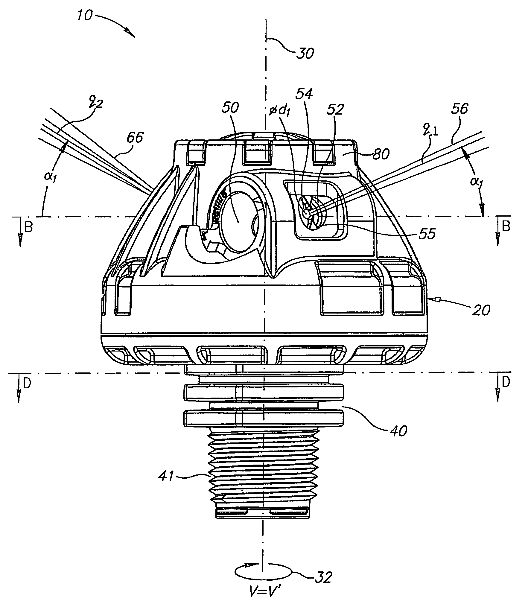
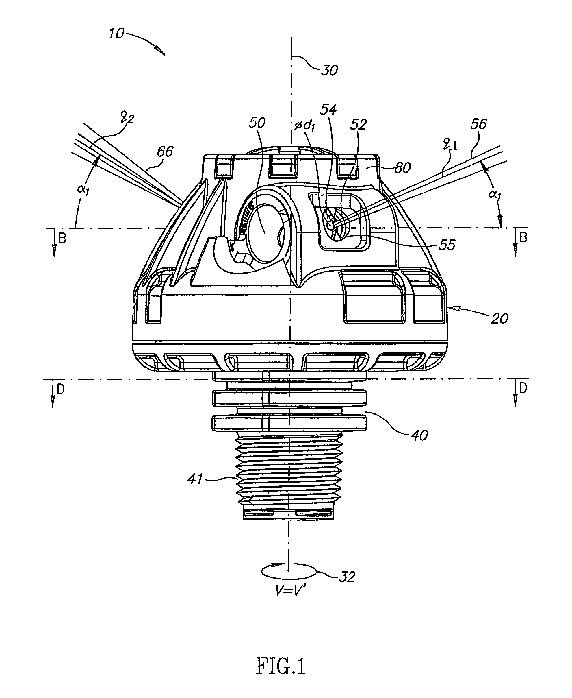
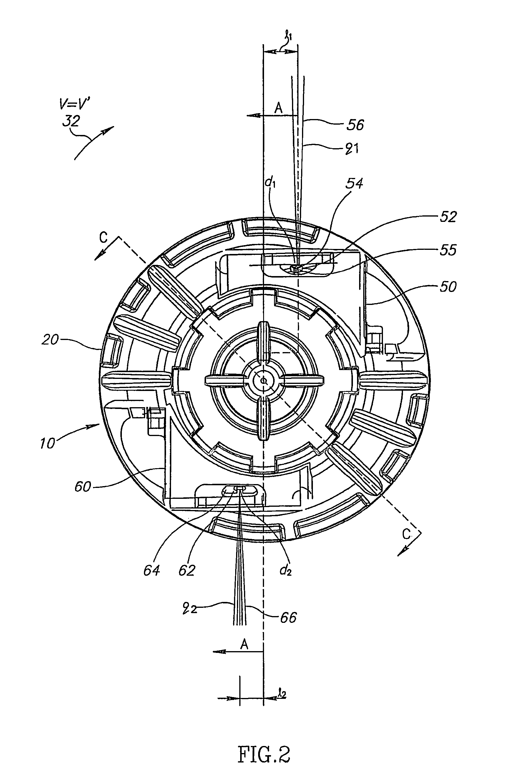
[0059]Let's refer to drawings number 1 and 2. The drawings depict a side view and a top view, respectively, of a revolving sprinkler 10 in accordance with the preferred embodiment of this invention.

[0060]Sprinkler 10 comprises a turret assembly 20 that is rotateable around a fixed axis 30. The rotateable turret assembly 20 is coupled via base assembly 40—that constitutes the body of the sprinkler, with the flow of the water under pressure (the manner of this coupling will be explained when describing drawings 4 to 6).

[0061]An option for mounting the sprinkler 10 on a means for conveying the water flow under pressure, is for example, mounting the sprinkler 10 on a peg that is linked to an irrigating pipe (peg and pipe are not illustrated). Employing for that purpose external threading 41 that is formed on base assembly 40 and constitutes an integral part of ...


PUM


Abstract

A revolving sprinkler comprises a rotatable turret assembly revolving around a rotation axis and formed with mouthpiece(s) suited to sprinkle liquid under pressure. The revolving sprinkler accommodates exchangeable mouthpieces with different throughputs-nozzle to rotation axis distance relationships, without changing a rotation velocity of the turret assembly.

Description

CROSS REFERENCE TO RELATED APPLICATIONS[0001]This application is a continuation of PCT International Application No. PCT / IL2004 / 000269 filed Mar. 24, 2004 and published in English as WO 2004 / 085077 A1 on Oct. 7, 2004 which claims priority of Israel application no. 155053 filed Mar. 24, 2003, the disclosures of which are hereby incorporated by reference herein in their entirety.FIELD OF THE INVENTION[0002]The present invention relates to the field of revolving sprinklers in general, and to those revolving sprinklers that are primarily intended for providing irrigation for cultivating agricultural areas in particular.BACKGROUND OF THE INVENTION[0003]Revolving sprinklers are widely used and very common for specific agricultural use as well as for wetting large areas, extinguishing fire, dish washers, etc. For the sake of simplicity, the background of the invention, as well as the description of the invention proper, will be described as they refer to the agricultural irrigation applica...

Claims


Application Information

Patent Timeline
Patent Type & Authority Patents(United States)
IPC IPC(8): B05B3/02B05B3/06B05B15/65B05B15/70B05B15/74
CPCB05B3/005B05B3/06B05B15/065B05B15/10B05B15/74B05B15/65
Inventor LUTZKI, MOSHE
Owner RIVULIS PLASTRO LTD
Learn More