
Automatic analyzer

a technology of automatic analysis and analyzer, which is applied in the field of automatic analyzer, can solve the problems of affecting measurement, difficult to remove air bubbles generated during analyzer operation, and difficult to remove air bubbles using those methods, and achieve the effect of accurate measurement results

Active Publication Date: 2008-12-02
HITACHI SCI SYST LTD +1
View PDF16 Cites 2 Cited by
  • Summary
  • Abstract
  • Description
  • Claims
  • Application Information

AI Technical Summary

Benefits of technology

The patent text describes new inventions that are being disclosed. The technical effects of these inventions are not specified in the text.

Problems solved by technology

However, those methods have a difficulty in removing fine air bubbles that are formed by, e.g., oxygen dissolved in the circulating water upon heating with a heater.
The known control methods are able to remove the air bubbles generated in an initial stage, e.g., at the time of exchange of the circulating water, but air bubbles generated during the analyzer operation are very difficult to remove with those methods.
Such a case raises a possibility that even those fine air bubbles, which have been free from problems in the past, may affect the measurement result.

Method used


Image

  • Automatic analyzer
  • Automatic analyzer
  • Automatic analyzer

Examples


embodiment 1

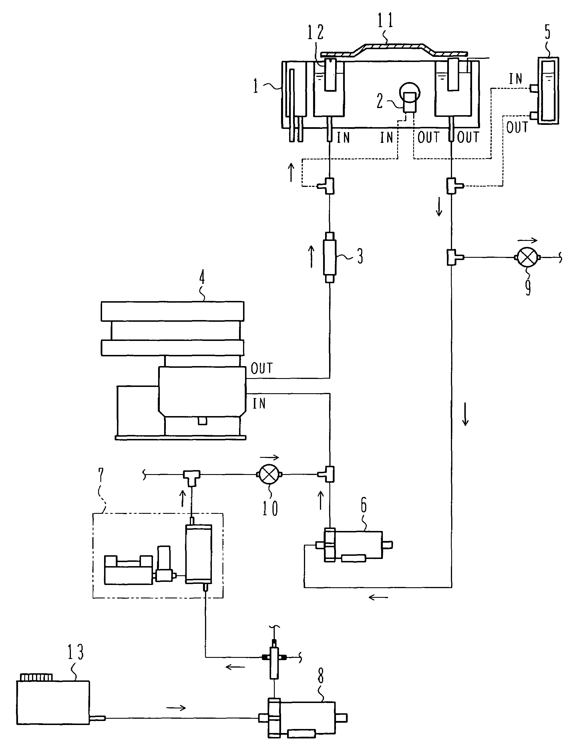
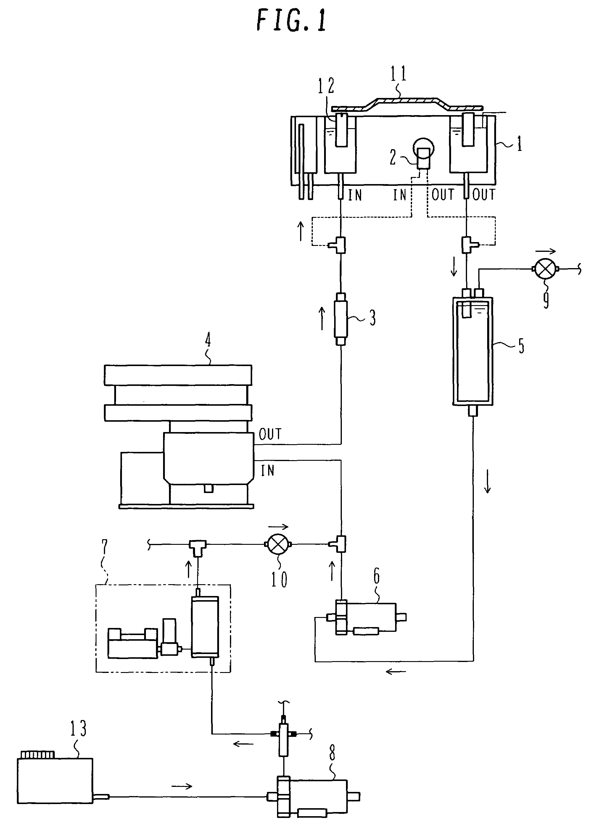
[0020]FIG. 1 is a schematic view showing a constant temperature bath of warm-water circulating type used in an automatic analyzer. To keep a sample and a reagent in each of reaction cells 12 mounted to a reaction table 11 at about 37° C., water in the constant temperature bath 1 (hereinafter referred to as “constant temperature bath water”) is held at a temperature of about 37° C. with on / off control of a heater 3. The automatic analyzer further comprises a circulation pump 6 for circulating the constant temperature bath water, a reagent cooling unit 4 for keeping cool reagents and for cooling the circulating water when the water temperature rises excessively, a pipe 2 used for cooling a photometer lamp, a solenoid valve 10 for water supply, a trap 5 for removing air bubbles (hereinafter also referred to as an “air-bubble removing unit”), and a solenoid valve 9 for water drain. Further, a water supply pump 8 for supplying water to the constant temperature bath and a degassing unit 7...

embodiment 2

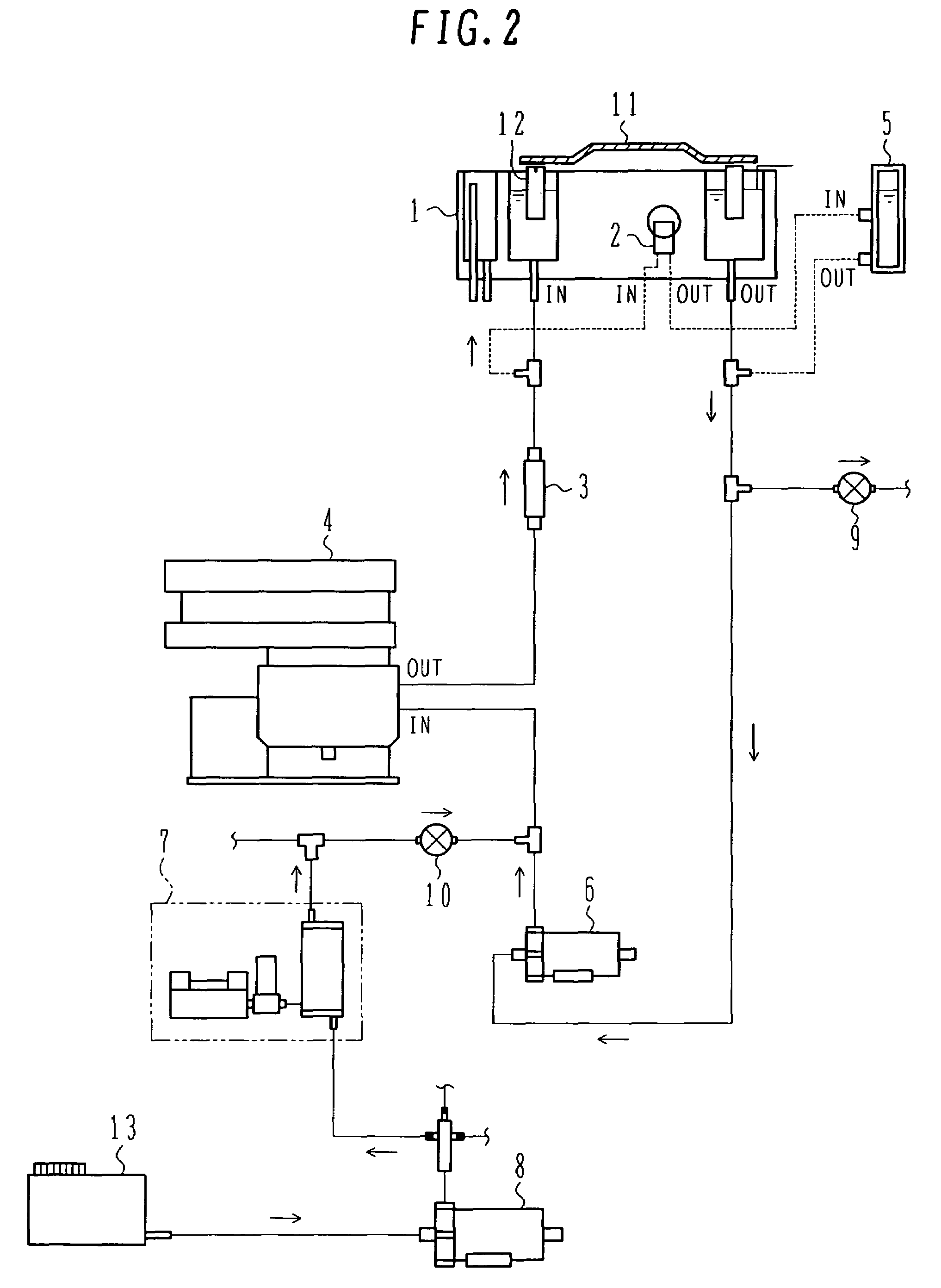
[0024]FIG. 2 is a schematic view of another embodiment in which the trap 5 is provided in a sub-channel. The trap 5 is provided to locate at the same level as the water surface in the reaction tank 1, and the top of the trap 5 is left open to the atmosphere. With such an arrangement, air bubbles accumulated in the trap 5 is naturally released out of the analyzer.

[0025]FIGS. 3A and 3B show comparative data of measurement results obtained with cell blank measurement (in which the measurement is performed by putting water, instead of a sample, in the reaction cell for calibration of values measured by the photometer) when the trap 5 is provided and when it is not provided. The vertical axis represents absorbance, and the horizontal axis represents the position number of each reaction cell (container) mounted to the reaction disk. As seen, when the trap 5 is not provided, the cell blank measured value varies depending on the cell position. This is presumably attributable to the fact tha...


PUM

PropertyMeasurementUnit
temperatureaaaaaaaaaa
constant temperatureaaaaaaaaaa
temperatureaaaaaaaaaa

Abstract

An automatic analyzer which can remove air bubbles in a photometric light path within a reaction tank and can provide accurate measurement results with stability. The automatic analyzer comprises a reaction cell for mixing a sample and a reagent therein, a constant temperature bath for holding water in which the reaction cell is immersed, a suction pipe for sucking the water in the constant temperature bath, a return pipe for returning the water to the constant temperature bath, a pump disposed between the suction pipe and the return pipe and circulating the water, a heater for heating the water circulated in the constant temperature bath by the pump, and an air-bubble removing unit disposed between the suction pipe and the return pipe, having a water-tight structure to hold the constant temperature bath water therein, and removing air bubbles based on a difference in gravity between the water and the air bubbles.

Description

BACKGROUND OF THE INVENTION[0001]1. Field of the Invention[0002]The present invention relates to an automatic analyzer for performing qualitative and quantitative analyses of biological samples, such as blood and urine, and more particularly to an automatic analyzer provided with a constant temperature bath for holding reaction cells at a certain temperature.[0003]2. Description of the Related Art[0004]An automatic analyzer capable of performing qualitative and quantitative analyses of target components in samples in a short time with high accuracy is employed in widespread fields, primarily in inspection centers and large-scaled hospitals which are required to analyze a large number of samples in a short time. The principle of such an automatic analyzer resides in utilizing a reagent which reacts with the target component and causes a chemical change, and analyzing a degree of the chemical change by using a photometer or the like.[0005]To maintain the reaction condition between the...

Claims


Application Information

Patent Timeline
Patent Type & Authority Patents(United States)
IPC IPC(8): G01N21/05G01N21/76B01L7/02G01N21/03G01N21/15G01N21/25G01N21/47G01N35/00G01N35/02
CPCB01L7/02G01N21/0332G01N21/4738G01N35/025B01L2200/0684G01N2035/00396
Inventor ISOBE, TETSUYATAKAHASHI, KATSUAKINISHIDA, MASAHARU
Owner HITACHI SCI SYST LTD
Learn More