Analytical tool and analytical system
an analytical tool and analytical system technology, applied in the field of analytical tools and analytical systems, can solve the problems of affecting the electrophoresis removing such interfering substances, and creating substances potentially interfering with proper analysis, so as to prevent the unintentional migration of liquid in the capillary tube and achieve stable analysis
- Summary
- Abstract
- Description
- Claims
- Application Information
AI Technical Summary
Benefits of technology
Problems solved by technology
Method used
Image
Examples
embodiment 2
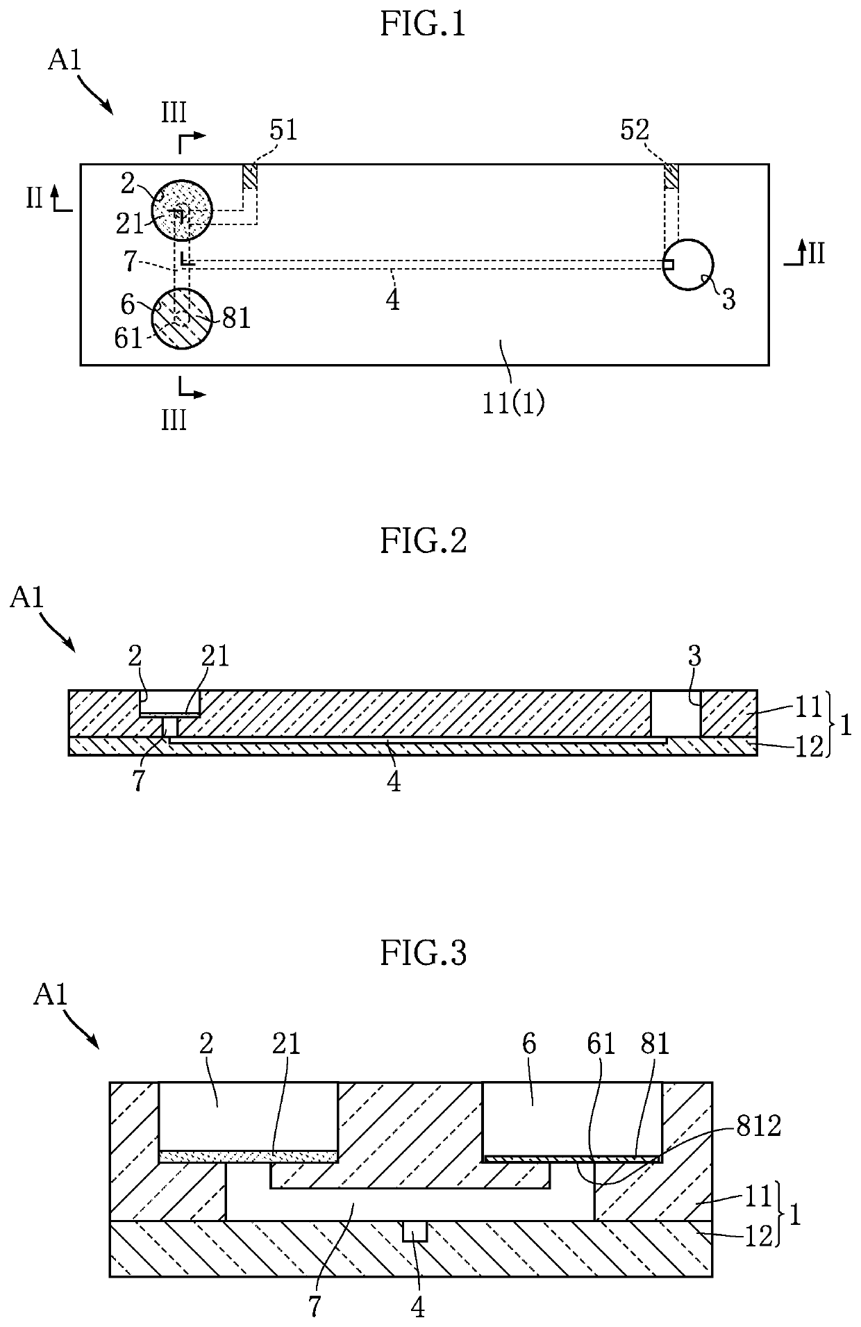
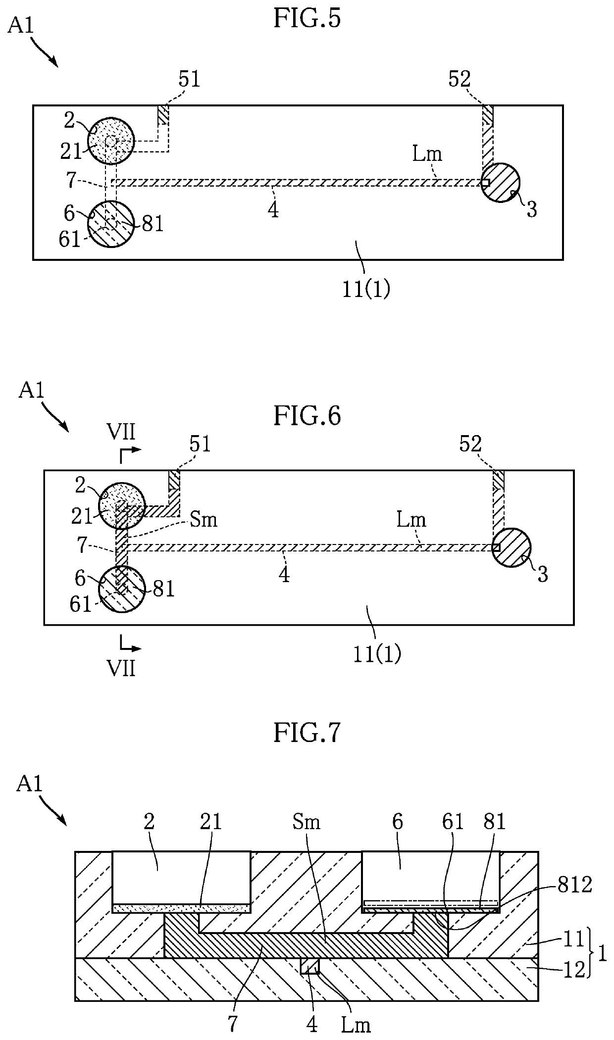
[0084]FIG. 12 shows an analytical tool of the present invention. The analytical tool A2 of this embodiment differs from the analytical tool A1 in that the flat member 81 does not have a hydrophilic surface 812 facing the enlarged portion 61. FIG. 13 is a graph showing the analytical result obtained by an analytical process using the analytical tool A2. Other than the configuration of the flat member 81, the analytical process of this embodiment is performed under the same conditions as the analytical process performed using the analytical tool A1. The graph of this embodiment shows clear peaks corresponding to the analyte components, indicating that the flat member 81 of this embodiment is effective to substantially reduce pressure fluctuations caused by the surface tension.
embodiment 3
[0085]FIG. 14 shows an analytical tool of the present invention. The analytical tool A3 of this embodiment differs from the analytical tools A1 and A2 described above in that the flat member 81 has a portion 811 fixed to the secondary reservoir 6. The fixed portion 811 is a portion of the flat member 81 secured to the bottom of the secondary reservoir 6 by heat fusing or adhesive. This configuration enables the flat member 81 to act as a value. This embodiment is effective to substantially reduce pressure fluctuations caused by the surface tension of the diluted sample Sm at the enlarged portion 61.
embodiment 4
[0086]FIG. 15 shows an analytical tool of the present invention. The analytical tool A4 of this embodiment differs from the foregoing embodiments in that the flat member 81, as well as the filter 21, is made of a porous medium that allows a liquid to pass through. Specific examples of porous mediums usable for the flat member 81 are the same as those for the filter 21. The flat member 81 of this embodiment is placed on the bottom of the secondary reservoir 6 without being fixed.
[0087]FIG. 16 is a graph showing the analytical result obtained by an analytical process using the analytical tool A4. Other than the configuration of the flat member 81, the analytical process of Embodiment 2 is performed under the same conditions as the analytical process performed using the analytical tool A1. The graph of this embodiment shows clear peaks corresponding to the analyte components, indicating that the flat member 81 made of a porous medium is effective to substantially reduce pressure fluct...
PUM
| Property | Measurement | Unit |
|---|---|---|
| Thickness | aaaaa | aaaaa |
| depth | aaaaa | aaaaa |
| width | aaaaa | aaaaa |
Abstract
Description
Claims
Application Information
 - R&D
- Intellectual Property
- Life Sciences
- Materials
- Tech Scout
- Unparalleled Data Quality
- Higher Quality Content
- 60% Fewer Hallucinations
Browse by: Latest US Patents, China's latest patents, Technical Efficacy Thesaurus, Application Domain, Technology Topic, Popular Technical Reports.
© 2025 PatSnap. All rights reserved.Legal|Privacy policy|Modern Slavery Act Transparency Statement|Sitemap|About US| Contact US: help@patsnap.com


