
Acoustic transducers for tubulars

a technology of acoustic transducers and tubulars, applied in instruments, surveying, borehole/well accessories, etc., can solve the problems of affecting reliability, affecting construction, and difficult to achieve shear wave measurements with pure monopole acoustic tools

Active Publication Date: 2008-12-02
SCHLUMBERGER TECH CORP
View PDF74 Cites 57 Cited by
  • Summary
  • Abstract
  • Description
  • Claims
  • Application Information

AI Technical Summary

Benefits of technology

The solution enables improved shear wave measurements and increased reliability by providing a compact, liquid-free, and robust transducer design that can effectively excite and detect acoustic modes in challenging subsurface conditions.

Problems solved by technology

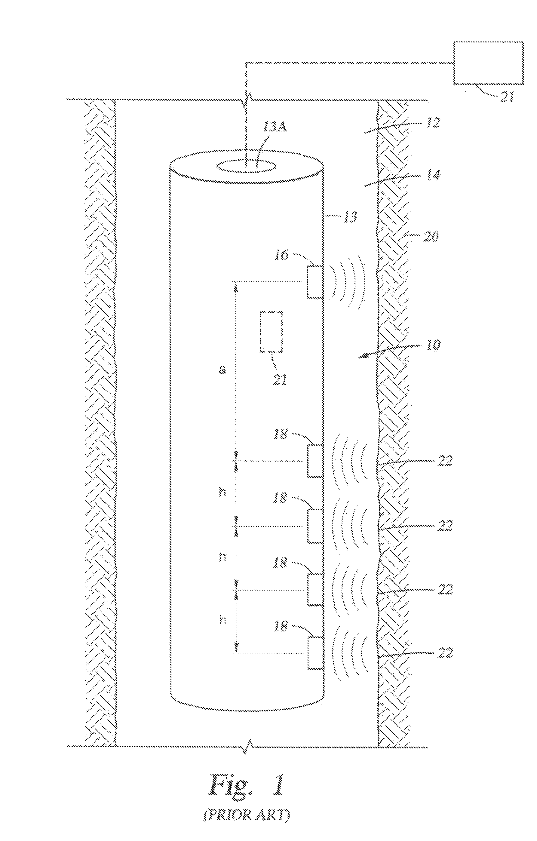
In large boreholes and slow rock formation conditions, shear wave measurements are difficult to achieve with pure monopole acoustic tools.
A drawback of the proposed transducers is the use of oil compensation in the assembly, which complicates construction and affects reliability.

Method used


Image

  • Acoustic transducers for tubulars
  • Acoustic transducers for tubulars
  • Acoustic transducers for tubulars

Examples


Embodiment Construction

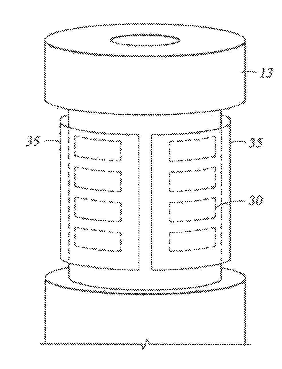
[0039]The present invention discloses acoustic transducers that can be implemented in multiple configurations and different diameters in order to fit any tubular. Embodiments of the invention make it possible to excite the wellbore's acoustic modes over a broad frequency range with improved mode purity excitation using a single transducer unit. The transducer design is based on transducer elements implemented in a semi-cylindrical or arch shaped configuration.

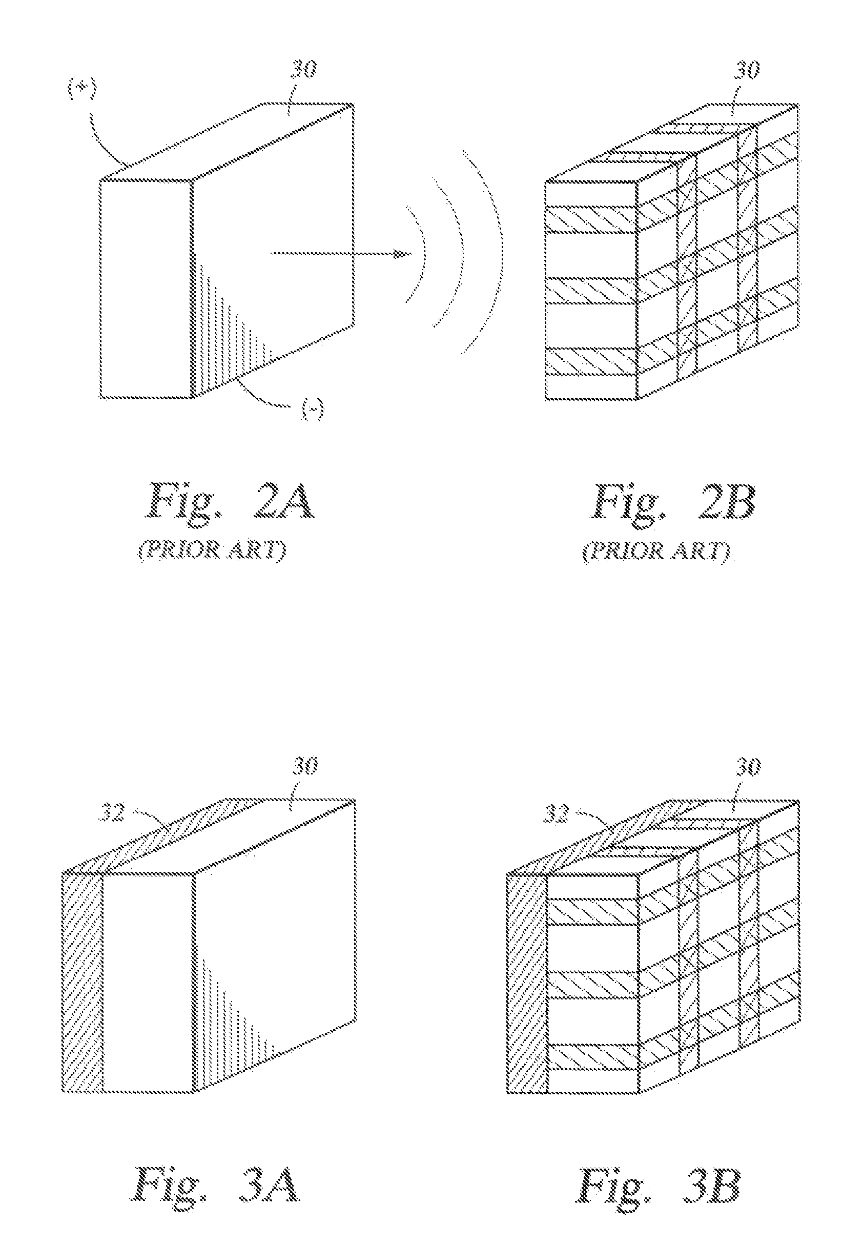
[0040]FIG. 2A shows a typical transducer element 30 implemented in the invention. The transducer element 30 may be a single or multilayer (stack) element to improve sound radiation and acoustic output pressure level. Useable elements 30 include piezoelectric devices, lead titanate (PT) devices, lead zirconate-titanate (PZT) devices, 1-3 piezocomposite type devices, or any other suitable material known in the art. The element 30 is preferably polarized in the thickness mode. When a positive voltage is applied to a planar surface...


PUM

PropertyMeasurementUnit
voltageaaaaaaaaaa
polarityaaaaaaaaaa
acoustic energyaaaaaaaaaa

Abstract

Acoustic transducers configured with transducer elements disposed on an arch or arcuate shaped member adapted to fit in juxtaposition around a tubular. The arcuate shaped member is adapted with conductors to provide a voltage to the transducer elements. One embodiment uses a metallic arcuate shaped member. Embodiments implemented as sources are used to excite borehole acoustic modes. Some embodiments provide phased array acoustic energy excitation / signal reception. The transducers are covered with a sealer in a liquid-free configuration and shields are used to protect the transducers.

Description

CROSS-REFERENCE TO RELATED APPLICATIONS[0001]This invention claims priority pursuant to 35 U.S.C. § 119 of U.S. Provisional Patent Application Ser. No. 60 / 535,062, filed on Jan. 8, 2004, and U.S. Provisional Patent Application Ser. No. 60 / 534,900, filed on Jan. 8, 2004. These Provisional Applications are hereby incorporated by reference in their entirety.BACKGROUND OF INVENTION[0002]1. Field of the Invention[0003]The invention relates generally to acoustic transducers. More particularly, this invention relates to improved acoustic transducers for use on tubulars.[0004]2. Background Art[0005]In the oil and gas industry, subsurface formations are typically probed by well logging instruments to determine the formation characteristics. Among these instruments, sonic tools have been found to provide valuable information regarding subsurface acoustic properties, which may be used to produce images or derive related characteristics for the formations.[0006]Acoustic waves are periodic vibra...

Claims


Application Information

Patent Timeline
Patent Type & Authority Patents(United States)
IPC IPC(8): G01V1/40G01V1/52H04R17/00E21B47/01G01NG01N29/00G01S7/521H04R1/00H04R1/02H04R17/02
CPCE21B47/011G01V1/52E21B47/017E21B47/01
Inventor GARCIA-OSUNA, FERNANDOMASSON, JEAN PIERRE
Owner SCHLUMBERGER TECH CORP
Learn More