Patient interface for spectroscopy applications

a technology for spectroscopy and patient interfaces, applied in the field of medical spectroscopy, can solve the problems of affecting the accuracy of spectroscopy, and the entanglement of patient interfaces or attachment straps,

Inactive Publication Date: 2008-12-02
HUTCHINSON TECH
View PDF48 Cites 26 Cited by
  • Summary
  • Abstract
  • Description
  • Claims
  • Application Information

AI Technical Summary

Benefits of technology

[0021]There is yet one more process for locating the patient interface on a patient, where the patient interface has a generally concave locating edge and a measurement side with a light transmission hole and a light receiving hole aligned generally along an axis bisecting the concave locating edge. The process includes the steps of locating the concave locating edge proximate the base of a digit and aligning the light transmission hole and the light receiving hole along a major muscle group to be measured.

Problems solved by technology

A problem with spectroscopy of fingers is that the patient interfaces or the attachment straps tend to wrap entirely around the finger.
Blood flow to the finger can be thereby restricted and this can affect the accuracy of the spectroscopy.
However, the prior art suffers from an inability to relocate the sensor easily once the sensor has been affixed to the tissue.

Method used


Image

  • Patient interface for spectroscopy applications
  • Patient interface for spectroscopy applications
  • Patient interface for spectroscopy applications

Examples


Embodiment Construction

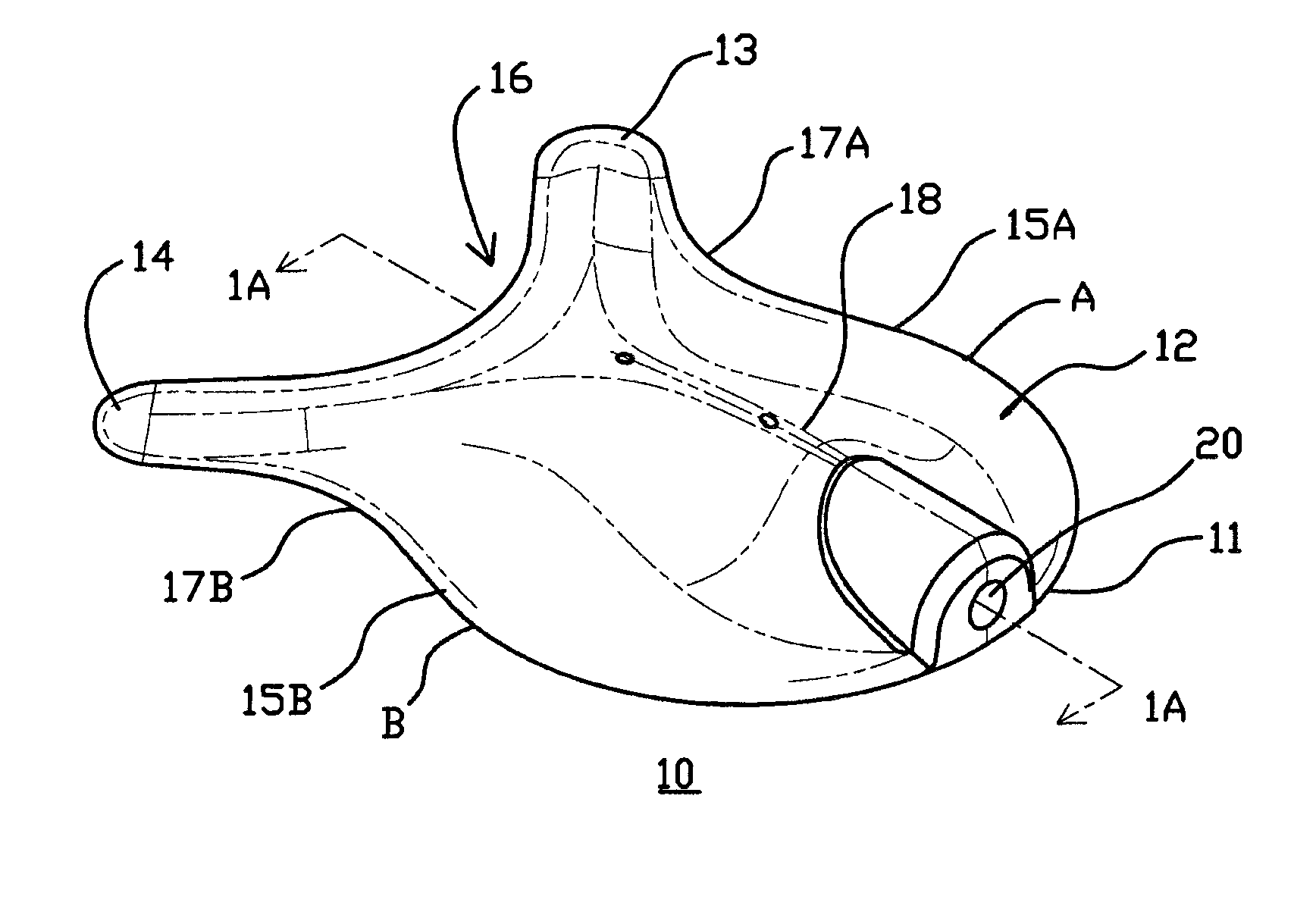
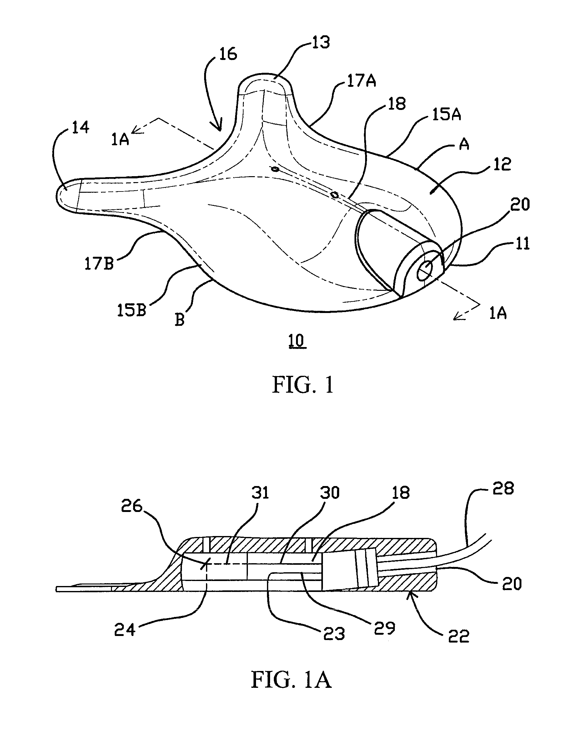
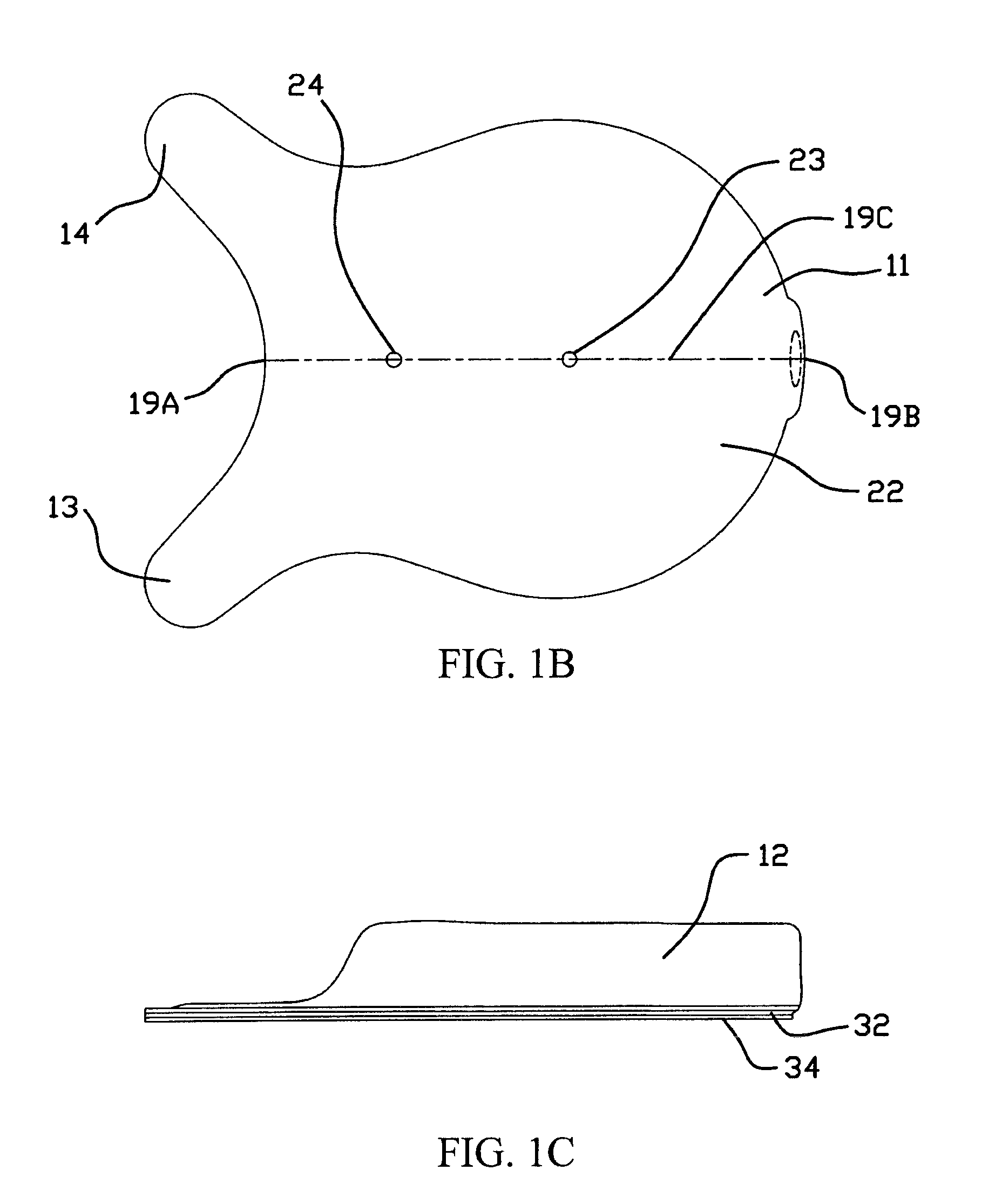
[0050]Referring now to FIG. 1, thereshown is a patient interface 10 for use with a tissue spectrometer (not shown). The patient interface includes base 12, wings 13 and 14, convex regions 15A and B, concave region 16, pocket 18 and opening 20. The base 12 may have a semi-circular portion between points A and B and extend in convex regions 15A and B. The convex regions are intended to engage peripheral portions of the thenar eminence or other sites when positioned for use on the hand. The convex regions are also intended to shield ambient light while engaging the peripheral portions of the thenar eminence. The convex regions 15A and B lead into concave regions 17A and B which are intended to roughly follow the narrowing of the thenar eminence or other sites at its distal end. Wings 13 and 14 are for partially wrapping around the thumb or other sites of the patient. Concave region 16 serves as a locating feature such as at the base of the thumb or other finger or a pediatric shoulder ...


PUM


Abstract

A patient interface and a method of installing a patient interface for a spectroscopy kit on a patient. The patient interface includes a butterfly-shaped patient interface with a cap on top of the patient interface and in proximity to an optical head.

Description

CLAIM OF PRIORITY[0001]This application is a continuation-in-part of application Ser. No. 11 / 129,935, filed May 16, 2005, and claims the benefit of application Ser. No. 60 / 790,462, filed Apr. 7, 2006, both entitled “PATIENT INTERFACE FOR SPECTROSCOPY APPLICATIONS.”BACKGROUND OF THE INVENTION[0002]The present invention relates to the field of medical spectroscopy and more specifically to the field of mounting sensors on a patient for use in spectroscopy.[0003]The use of spectroscopy in medical condition diagnosis has become commonplace. Typically, light is placed on the surface of tissue in one location and transmitted or scattered light is collected from the tissue in another location. A spectral analysis of the collected light is then performed and the results are compared to stored information about spectral profiles of tissue having known conditions. From this comparison, the condition of the tissue under study may be determined.[0004]The light to be transmitted into the tissue i...

Claims


Application Information

Patent Timeline
Patent Type & Authority Patents(United States)
IPC IPC(8): A61B5/1455
CPCA61B5/0059A61B5/026A61B5/14535A61B5/14552A61B5/6826A61B5/6833A61B5/6838A61B5/6824A61B2562/164
Inventor FLESSLAND, LARRY D.ORTNER, JOSEPH P.SCHEELE, BRYAN J.SCHEELE, DANIEL W.
Owner HUTCHINSON TECH
Why Eureka
Try Eureka