Methods for spectrally calibrating CT imaging apparatus detectors

a computed tomography and detector technology, applied in tomography, instruments, applications, etc., can solve the problems of long calibration time and effort expended in producing

Inactive Publication Date: 2006-08-08
GENERAL ELECTRIC CO
View PDF12 Cites 22 Cited by
  • Summary
  • Abstract
  • Description
  • Claims
  • Application Information

AI Technical Summary

Benefits of technology

[0007]Configurations of the present invention in principle do not require the scanning of phantoms. Instead, some configurations of the present invention are able to determine x-ray detection efficiency as a function of photon energy for individual detector elements by measuring x-ray projections through air at multiple kVps. With the detection efficiencies thus determined, spectral errors for an x-ray spectrum attenuated through any given size of water-like object can also be determined. Configurations of the present invention thus can be performed in the time required for conventional air calibrations and can be fully automated, making daily spectral calibration feasible. Moreover, some configurations of the present invention enable spectral calibration of arbitrary or dynamically varying beam filters (such as bow tie filters) that can be used to reduce radiation dose to the patient, even through physical calibration is not necessarily performed with a shape of a particular beam filter.

Problems solved by technology

Thus, effort has to be expended to produce and select detector elements with nearly identical spectral characteristics.
Inaccurate determination of spectral response differences between detector elements results in rings and bands in images around the iso-center.
However, multiple phantoms of various sizes are often required to cover the attenuation range needed for some types of imaging, including medical imaging, leading to lengthy calibration times. Spectral calibration is often performed every few months.

Method used


Image

  • Methods for spectrally calibrating CT imaging apparatus detectors
  • Methods for spectrally calibrating CT imaging apparatus detectors
  • Methods for spectrally calibrating CT imaging apparatus detectors

Examples


Embodiment Construction

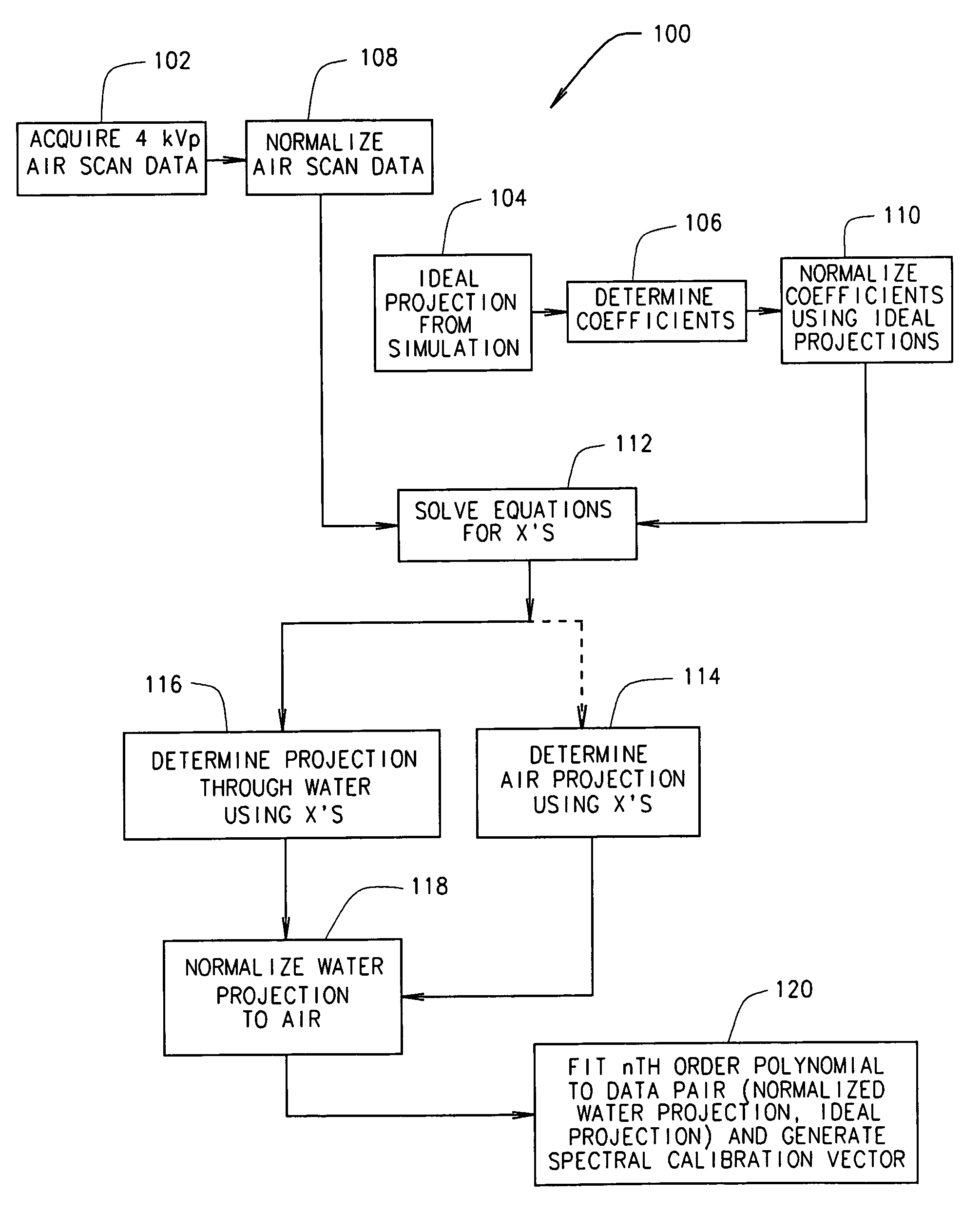
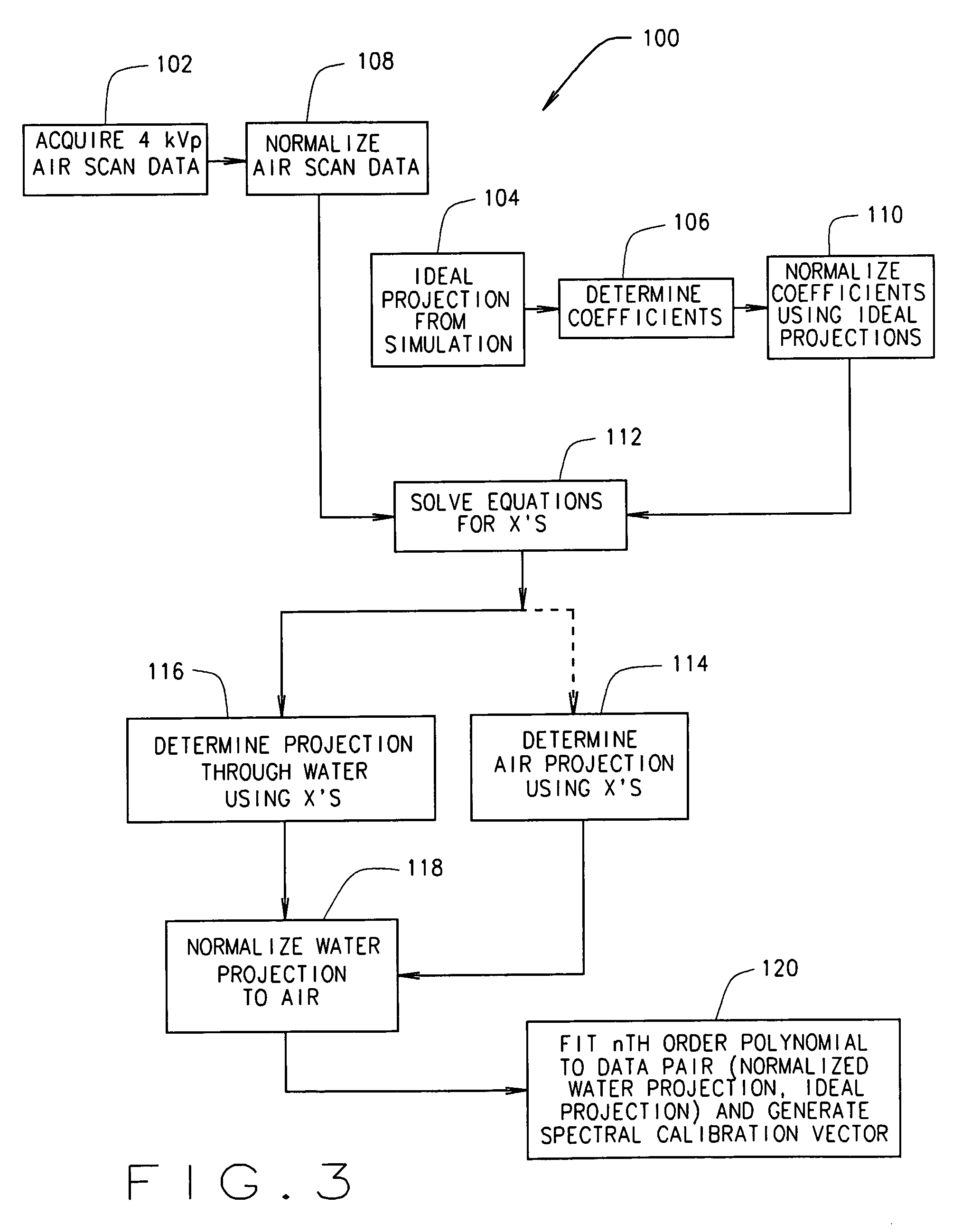
[0011]Example embodiments of methods and apparatus that facilitate calibration of CT imaging apparatus and CT imaging methods and apparatus having reduced image artifacts are described below in detail. A technical effect of the methods and apparatus described herein include at least one of calibration of CT imaging apparatus, reduction of image artifacts, and the determination of detector element detection efficiency as a function of photon energy for individual detector elements.

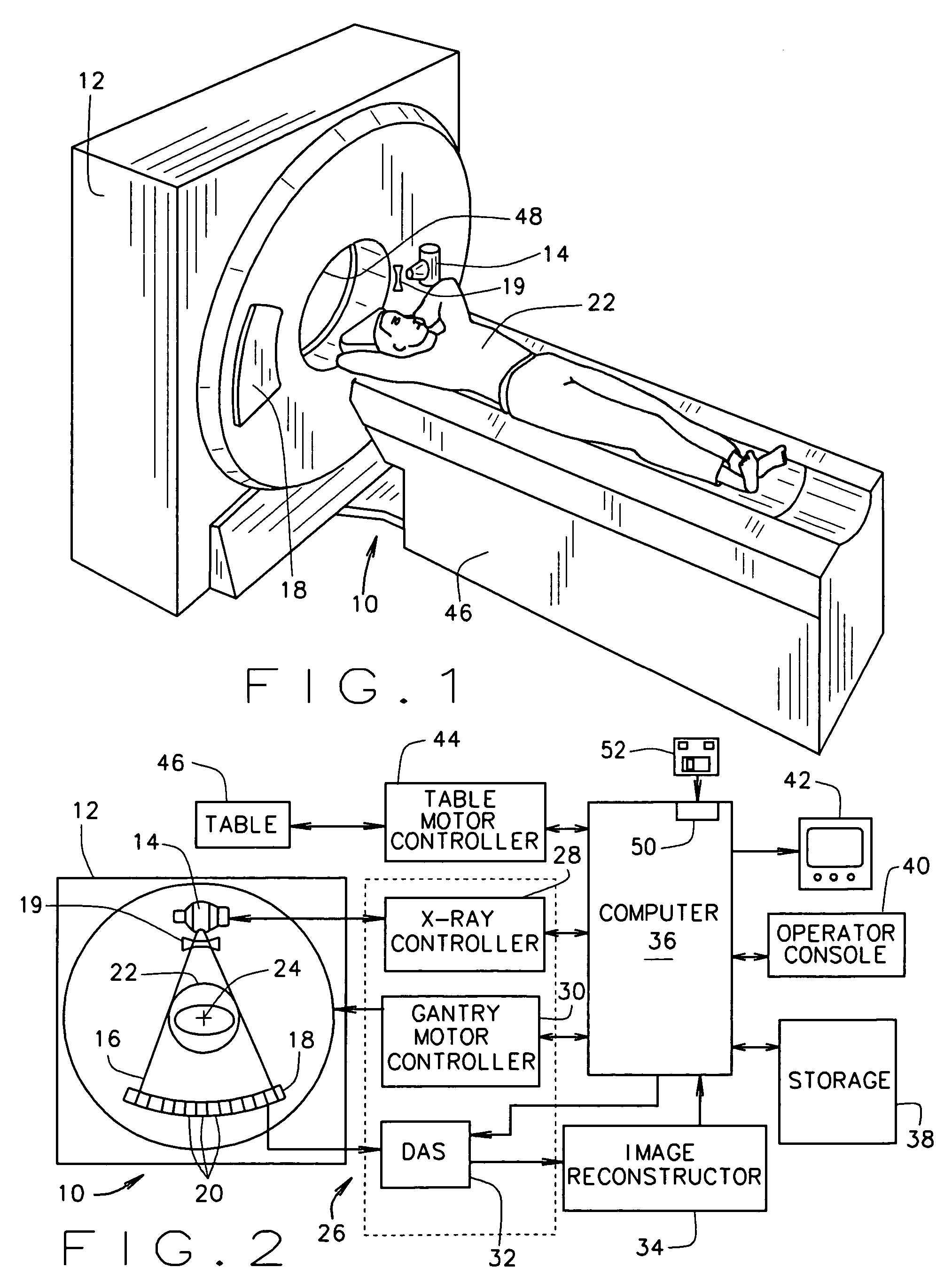
[0012]In some known CT imaging system configurations, an x-ray source projects a fan-shaped beam which is collimated to lie within an X-Y plane of a Cartesian coordinate system and generally referred to as an “imaging plane”. The x-ray beam passes through an object being imaged, such as a patient. The beam, after being attenuated by the object, impinges upon an array of radiation detectors. The intensity of the attenuated radiation beam received at the detector array is dependent upon the attenuation of an ...


PUM

PropertyMeasurementUnit
energy bandwidthsaaaaaaaaaa
thicknessaaaaaaaaaa
shapesaaaaaaaaaa

Abstract

A method for calibrating a computed tomographic imaging apparatus having a gantry, a radiation source operable at a plurality of kVp's, and a detector array having a plurality of detector elements includes using a system detection function to estimate signals of each detector element that would have been detected through air and through a given thickness of water to determine estimated datasets. The estimated datasets are used to determine data pair sets each comprising a normalized water projection value and an ideal projection value for each detector element. The method further includes determining and storing a representation of a mapping function of the normalized water projections values to the ideal projection values in a memory of the computed tomographic imaging apparatus as a spectral calibration of the computed tomographic imaging apparatus.

Description

BACKGROUND OF THE INVENTION[0001]This invention relates generally to methods for computed tomography (CT) imaging and more particularly to methods and apparatus for calibrating CT imaging apparatus detectors to produce images having reduced artifacts.[0002]X-ray CT measures x-ray attenuation through an object with a plurality of detector elements at various angular positions with respect to the object. With appropriate data processing, a cross-sectional image revealing inner structures of the object can be reconstructed. Reconstructed images represent a property of an object in response to x-rays (or other radiation), namely, the x-ray (or other radiation) linear attenuation. To reconstruct artifact free images, calibration of an CT imaging system and an appropriate correction must to be applied in the reconstruction process. For example, calibration and correction related detector response to incident x-ray spectrum must be performed. X-ray spectra often have wide energy bandwidths...

Claims


Application Information

Patent Timeline
Patent Type & Authority Patents(United States)
IPC IPC(8): G01D18/00A61B6/00A61B6/03G01N23/00G21K1/12H05G1/60
CPCA61B6/032A61B6/585A61B6/583
Inventor WU, XIAOYEBROMBERG, NEIL BARRYKOLKER, ALEXANDERSIMONI, PIERO UGOTOTH, THOMAS LOUIS
Owner GENERAL ELECTRIC CO
Why Eureka
Try Eureka