
Light sources for spectrally controlled interferometry

a light source and interferometer technology, applied in the field of interferometry, can solve the problems of reducing the utility of spectrally modulated sources, reducing the efficiency and reducing the cost and accuracy of measurement, so as to improve the utility of spectral modulation sources.

Active Publication Date: 2014-08-19
OLSZAK ARTUR
View PDF1 Cites 23 Cited by
  • Summary
  • Abstract
  • Description
  • Claims
  • Application Information

AI Technical Summary

Benefits of technology

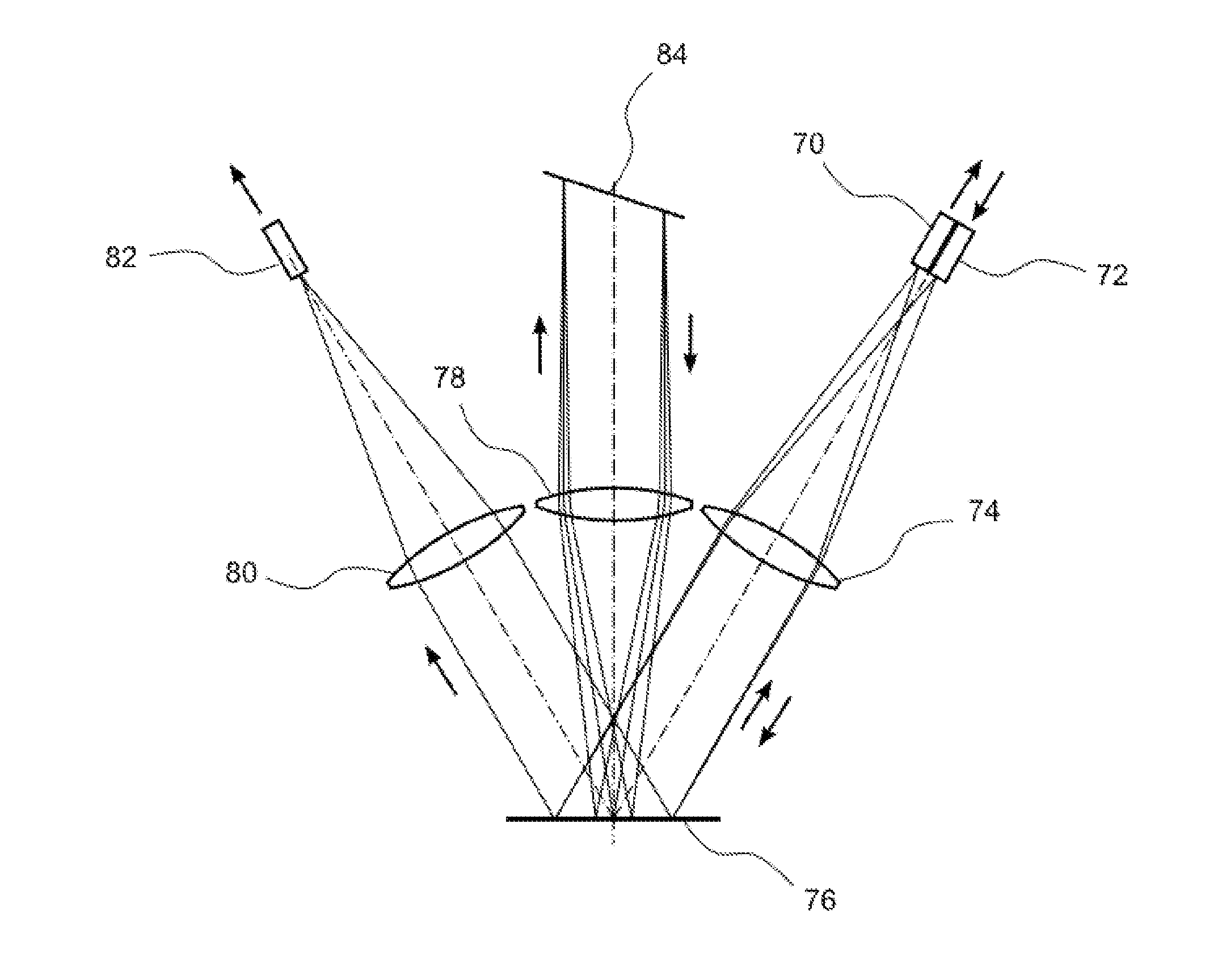
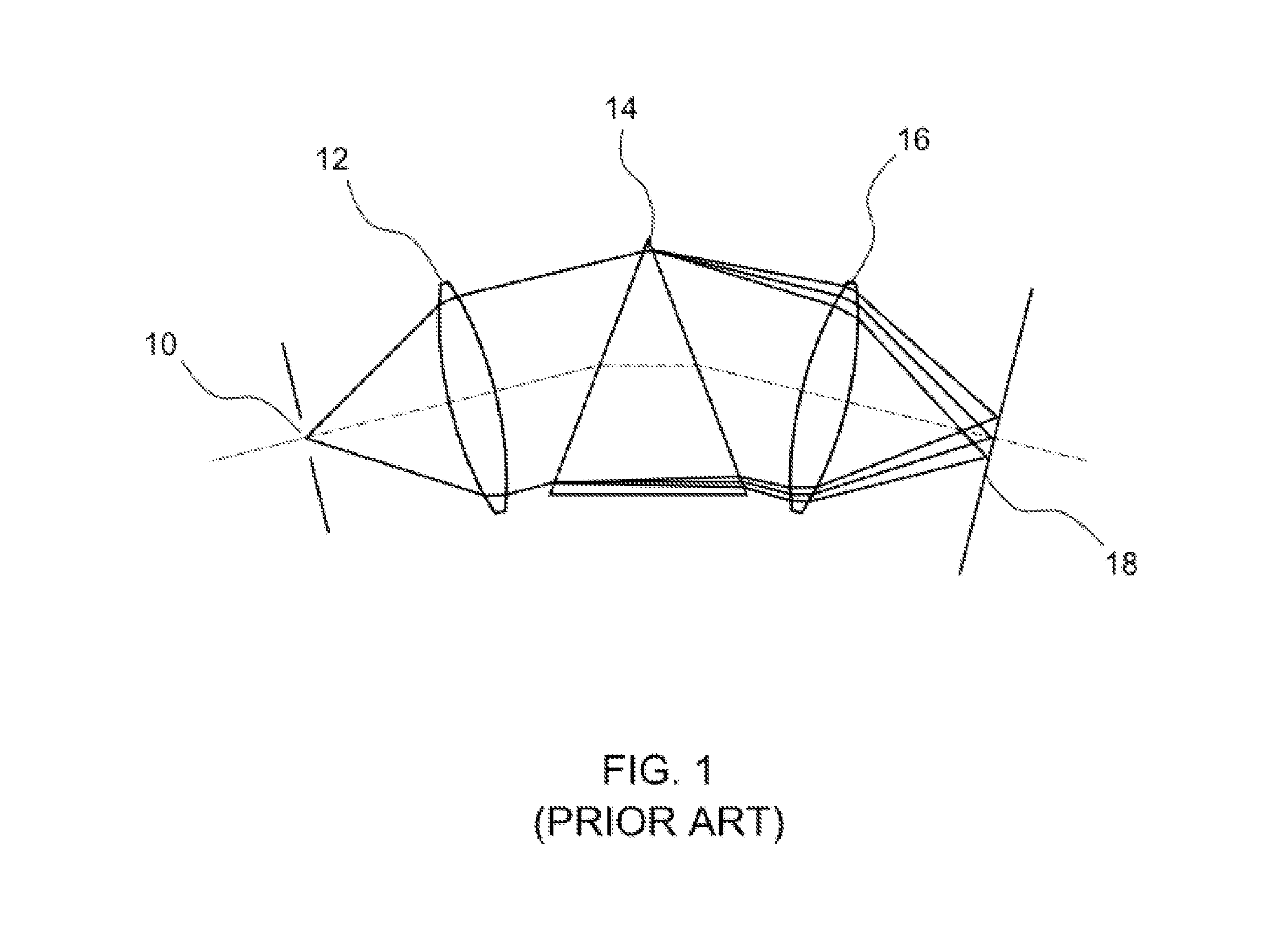
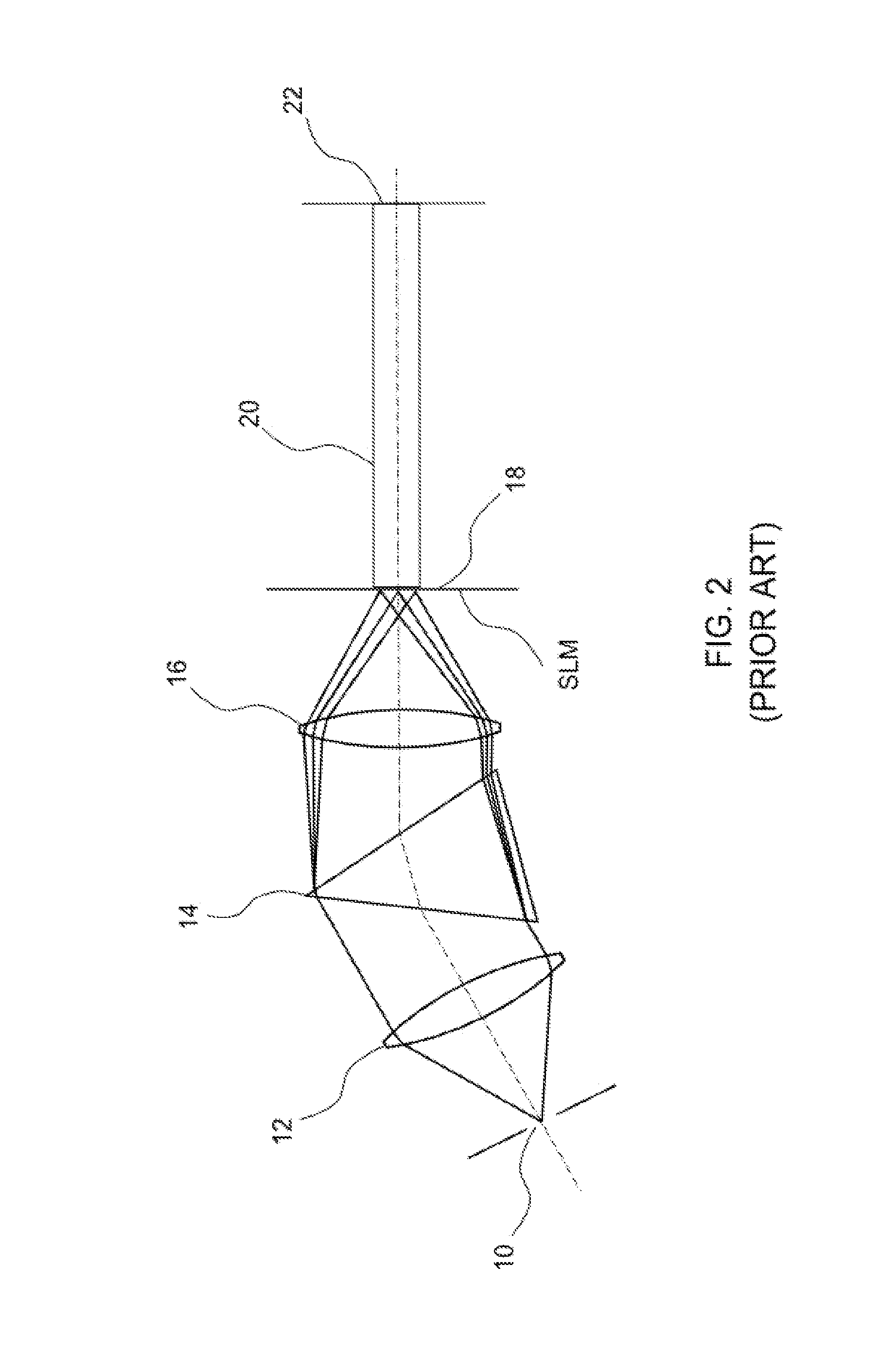
The invention is a special light source that can produce multiple copies of its spectral distribution on an image plane with a specific pattern. Each copy is passed through a modulating element with a different filter period, resulting in different modulated outputs. By selecting the spatial period of the light source and the filter period of the modulating element, a resonance effect is created that greatly improves the performance of the spectrally controlled light source.

Problems solved by technology

Its popularity can be attributed mainly to the use of common-path interferometer designs—a type of device in which the reference and test beams follow the same path inside the interferometer resulting in optical-system errors canceling out, which enables less expensive and more accurate measurements.
However, common-path interferometers can be implemented only with laser sources because the need for non-zero optical path difference (OPD) requires a high temporal-coherence source and corresponding non-localized interference.
These interferometers are immune to the coherent noise present with laser sources but require careful balancing of the OPD so interference can take place in the measurement space.
Such arrangements can be complex and prevent the use of common-path designs, therefore forfeiting its advantages.
Shrinking the width of the light source, however, reduces the amount of light that enters the system and the image progressively becomes dimmer.
This problem has been studied well in classical spectroscopy and is considered a fundamental limitation of this type of device.
The basic problem with such arrangements is the trade-off between the spectral resolution and the amount of useful energy in the spectrally filtered beam.
However, such devices need a similar level of control as laser diodes (LD) for both current and temperature, which requires expensive electronics and heat sinks.
Also, their emission spectra are typically located in the far-red spectrum and infrared, making them less useful for interferometry where the typical operating wavelength is 632.8 nm.

Method used


Image

  • Light sources for spectrally controlled interferometry
  • Light sources for spectrally controlled interferometry
  • Light sources for spectrally controlled interferometry

Examples


Embodiment Construction

[0027]As used in this disclosure, “white light” is intended to refer to any broadband light of the type used in the art of white-light interferometry, typically having a bandwidth on the order of many nanometers. With reference to light, the terms “frequency” and “wavelength” are used alternatively, as commonly done in the art, because of their well known inverse relationship. “OPD” and “time delay” are used alternatively because of their space / time relationship in interferometry. Similarly, “sine” and “cosine,” as well as related terms, are used alternatively unless specifically indicated otherwise. As used herein, the terms “modulate” and “modulation” in connection with a light source refer in the broadest sense to include any alteration of the frequency distribution, amplitude distribution or phase distribution of energy produced by the light source, and the synthesis of a light signal having a desired frequency, amplitude and phase distribution by any means. With reference to a ...


PUM

PropertyMeasurementUnit
angleaaaaaaaaaa
integration timeaaaaaaaaaa
white light interferometryaaaaaaaaaa

Abstract

A spectrally controlled light source includes a light source with a spectral distribution repeated with a predetermined spatial period along an input plane so as to produce multiple copies of the spectral distribution separated by the spatial period. All copies are propagated through dispersive optics to produce equally dispersed spectra on an image plane. A periodic modulating element with a given filter period is applied to each of the dispersed spectra to produce corresponding modulated outputs. According to the invention, the spatial period of the light source on the image plane and the filter period of the modulating element are selected so as to produce a resonance effect that greatly enhances the utility of the spectrally modulated source.

Description

RELATED APPLICATIONS[0001]This application is based on and claims the benefit of priority of U.S. Provisional Application No. 61 / 598,887, filed Feb. 14, 2012, which is hereby incorporated by reference in its entirety.BACKGROUND OF THE INVENTION[0002]1. Field of the Invention[0003]This invention relates in general to the field of interferometry and, in particular, to a novel light source for spectrally controlled interferometry.[0004]2. Description of the Prior Art[0005]Laser interferometry is a highly successful technique for measuring optical surfaces such as lenses and flats. Its popularity can be attributed mainly to the use of common-path interferometer designs—a type of device in which the reference and test beams follow the same path inside the interferometer resulting in optical-system errors canceling out, which enables less expensive and more accurate measurements. However, common-path interferometers can be implemented only with laser sources because the need for non-zero ...

Claims


Application Information

Patent Timeline
Patent Type & Authority Patents(United States)
IPC IPC(8): G02B26/00
CPCG02B27/1086C08L69/00G02B26/00C08L23/02C08L67/04C08J5/045C08L101/16C08J2300/16C08L23/12C08L25/04C08L27/06C08L67/02G02B26/0833G02B26/007C08L97/02
Inventor OLSZAK, ARTUR
Owner OLSZAK ARTUR
Learn More