
Measurement device and method for measuring electric signal from biological sample

a biological sample and measurement device technology, applied in the direction of instruments, laboratory glassware, investigating phase/state change, etc., can solve the problems of weak point of fluorochrome methods, inability to eliminate the influence of dyes on cells, and inability to detect weak points

Active Publication Date: 2008-12-09
PANASONIC CORP
View PDF11 Cites 14 Cited by
  • Summary
  • Abstract
  • Description
  • Claims
  • Application Information

AI Technical Summary

Benefits of technology

[0022]Thus, measurement stability against disturbances such as a solution flow can be improved.
[0029]Thus, by appropriately adjusting the interfacial tension in each of the first and second resistance baths, the location of an interface of the electrolyte solution can be controlled in a simple manner so that the interface is located in a desired position in each of the first and second communicating tubes.
[0033]Thus, even in a narrow region, each of the first and second resistors can have a great length, so that a large resistance value can be obtained.
[0035]Thus, the position of the biological sample contained in the electrolyte solution can be freely controlled. Furthermore, the degree of freedom of position control of the biological sample contained in the electrolyte solution is increased, so that the microelectrode can be freely formed in the well. That is, the degree of freedom of design of the inside of the well is improved.
[0041]According to the measurement method of the present invention, when electrophysiological measurement of a biological sample led by an electrode, a highly accurate position controller and skilled operation, which have been conventionally needed, are no longer necessary. That is, electrophysiological measurement of a biological sample can be performed in a simple, accurate, high-speed and automatic manner.
[0045]Thus, an electrical reaction of a biological sample to a drug can be measured in a simple manner.

Problems solved by technology

Therefore, influence of a dye to a cell can not be eliminated.
Moreover, in fluorochrome methods, fluorescence from a fluorochrome is weakened with time, so that detection accuracy becomes poor.
This is a weak point of fluorochrome methods.
Accordingly, the micropipette electrode methods are not suitable as a technique for screening a large amount of compounds as candidates for drugs at high speed.

Method used


Image

  • Measurement device and method for measuring electric signal from biological sample
  • Measurement device and method for measuring electric signal from biological sample
  • Measurement device and method for measuring electric signal from biological sample

Examples


embodiment 1

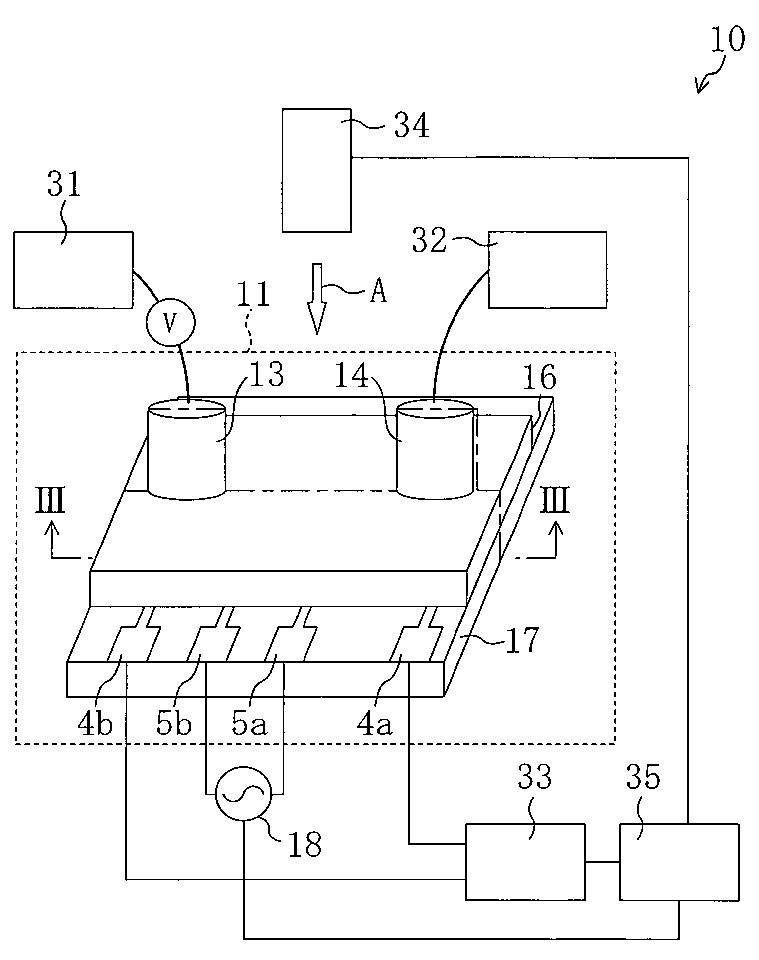
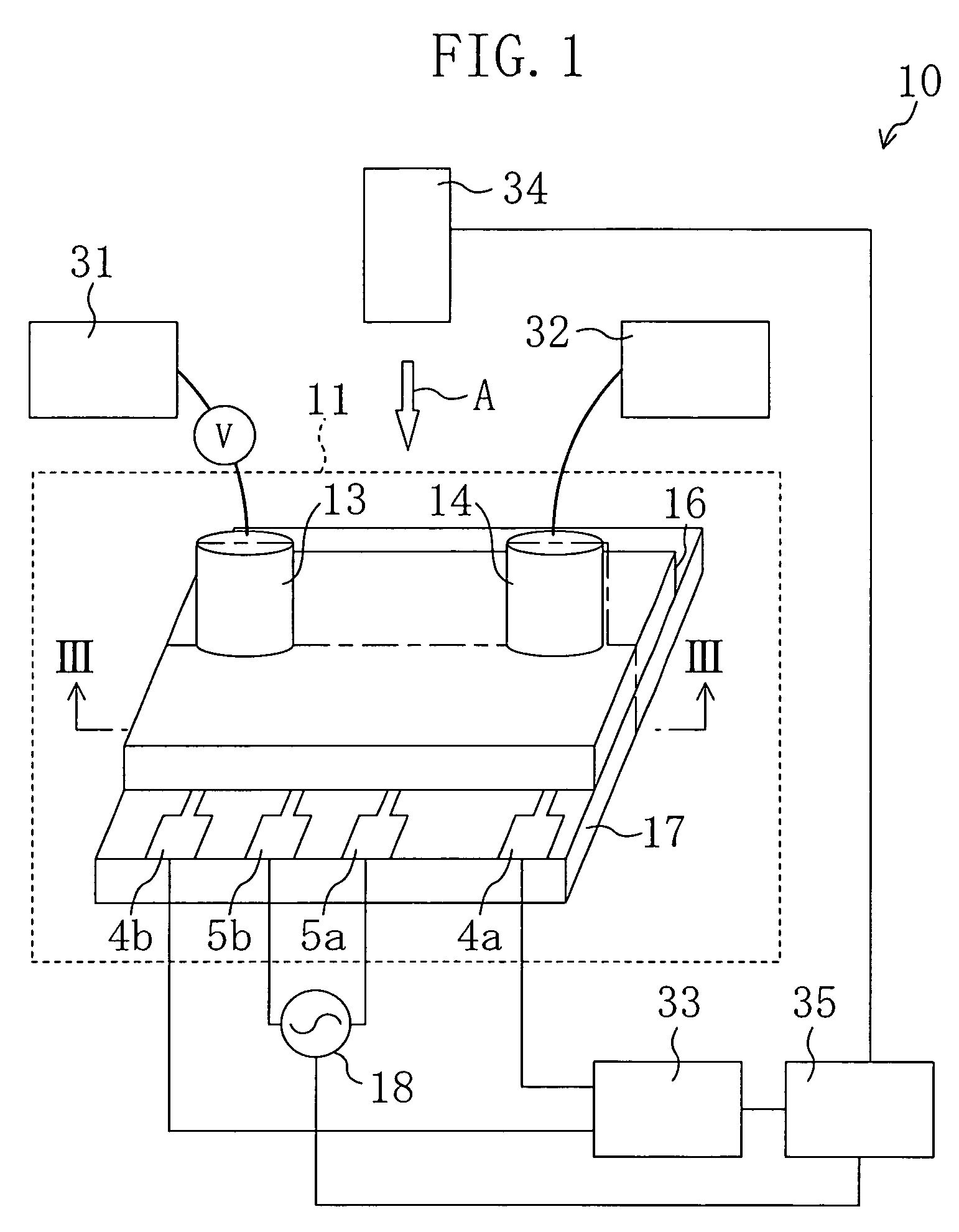
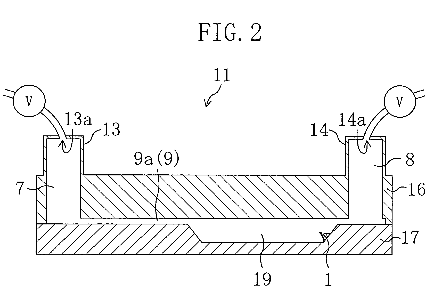
[0060]FIG. 1 is a diagram illustrating the structure of a measurement device according to this embodiment. FIG. 2 is a cross-sectional view taken along the line III-III of FIG. 1.

[0061]As shown in FIG. 1, a measurement device 10 according to this embodiment includes a measurement cell 11, a current application section 18, pumps 31 and 32, a measuring section 33, an imaging section 34, and a calculator 35.

[0062]The measurement cell 11 includes a substrate 17, a substrate 16 provided on the substrate 17. The substrates 16 and 17 are bonded to each other. As shown in FIG. 1, terminals 4a, 4b, 5a and 5b are provided on the substrate 17.

[0063]The current application section 18 is, as shown in FIG. 1, electrically connected to the terminals 5a and 5b provided on the substrate 17.

[0064]The pumps 31 and 32 are, as shown in FIG. 1, connected to opening portions 13a and 14a formed in an inlet connector 13 and an outlet connector 14, respectively.

[0065]The measuring section 33 is connected to ...

embodiment 2

[0130]In this embodiment, a measurement cell 11′ which can be used instead of the measurement cell 11 in the measurement device 10 of EMBODIMENT 1 will be described with reference to the accompanying drawings. Note that each member also shown in EMBODIMENT 1 is identified by the same reference numeral for the purpose of simplicity.

[0131]The measurement cell 11′ of this embodiment has substantially the same appearance as that of the measurement cell 11 of EMBODIMENT 1. Thus, in this embodiment, a case where the measurement cell 11 is replaced by the measurement cell 11′ will be described.

[0132]FIG. 7 is a cross-sectional view taken along the line III-III of FIG. 1. FIG. 8 is a perspective view of the measurement cell 11′ seen from the arrow A of FIG. 1. Note that a cross-sectional view taken along the line III-III of FIG. 8 corresponds to the cross-sectional view of FIG. 7. Moreover, in FIG. 8, the substrate 16 of the measurement cell 11′ is omitted.

[0133]The measurement cell 11′ has...

embodiment 3

[0142]FIG. 9 is a diagram illustrating the structure of a measurement device of this embodiment.

[0143]As shown in FIG. 9, the measurement device 10′ of this embodiment includes the measurement cell 11 or the measurement cell 11′, as the measurement device 10 of EMBODIMENT 1 or EMBODIMENT 2. More specifically, in the measurement device 10′ of this embodiment, the measurement cell 11 or the measurement cell 11′ is provided plural in number. The plurality of measurement cells 11 or 11′ are integrated in a matrix pattern. The structure of the measurement cell 11 or 11′ is exactly the same as that of EMBODIMENT 1 or EMBODIMENT 2.

[0144]Inlet connectors 13 and outlet connectors 14 provided in each of the plurality of measurement cells 11 or 11′ are connected to flow pass switchers 38 each including a valve and a pump. A structure is used in which the inlet connectors 13 and the outlet connectors 14 are made to be interchangeably used as outlets and as inlets by the flow pass switcher 38.

[0...


PUM

PropertyMeasurementUnit
diameteraaaaaaaaaa
angleaaaaaaaaaa
depthaaaaaaaaaa

Abstract

A measurement device 10 includes a measurement cell 11. The measurement cell 11 includes a substrates 17 and a substrate 16 formed on the substrate 17. The substrates 16 and 17 are bonded to each other. Thus, a flow pass 9 is formed in the measurement cell 11. As shown in FIG. 3, on the substrate 17 of the measurement cell 11, provided are a concave well 19, a protruding microelectrode 1 connected to a terminal 4a and formed on a side wall surface of the well 19, communicating tubes 15a and 15b connected to both of side surfaces of the well 19 (i.e., the flow pass 9) to face to each other, resistance baths 6a and 6b connected to the communicating tubes 15a and 15b, thin film resistors 3a and 3b arranged in the resistance baths 6a and 6b, and a reference electrode 2 connected to a terminal 4b.

Description

TECHNICAL FIELD[0001]The present invention relates to a measurement device for electrophysiological evaluation of a biological sample.BACKGROUND ART[0002]Conventionally, in chemical screening using a biological sample (represented by a cell), the action of a cell is monitored by fluorochrome method or a micropipette electrode method to evaluate the action and effect of a drug for the cell.[0003]Fluorochrome methods are methods for optically measuring, using fluorochromes which specifically react with various ion concentrations and a membrane-potential-sensitive fluorochrome, the action of a cell which is influenced by a drug, i.e., the degree of change in fluorescence of the cell according to changes in the membrane potential and ion concentration of the cell. In fluorochrome methods, the step of staining a cell with a dye is necessary. Therefore, influence of a dye to a cell can not be eliminated. Moreover, in fluorochrome methods, fluorescence from a fluorochrome is weakened with ...

Claims


Application Information

Patent Timeline
Patent Type & Authority Patents(United States)
IPC IPC(8): G01N27/00G01N15/06G01N25/18G01N33/53B01L3/00G01N33/487
CPCG01N33/48707B01L3/5027
Inventor OZAKI, NOBUHIKOOKA, HIROAKISUGIHARA, HIROKAZU
Owner PANASONIC CORP
Learn More