Measurement device for measuring electric signal emitted by biological sample
a biological sample and measurement device technology, applied in the direction of instruments, laboratory glassware, investigating phase/state change, etc., can solve the problems of weakening the fluorochrome method, the influence of a dye on a cell cannot be eliminated, and the detection accuracy becomes poor
- Summary
- Abstract
- Description
- Claims
- Application Information
AI Technical Summary
Benefits of technology
Problems solved by technology
Method used
Image
Examples
embodiment 1
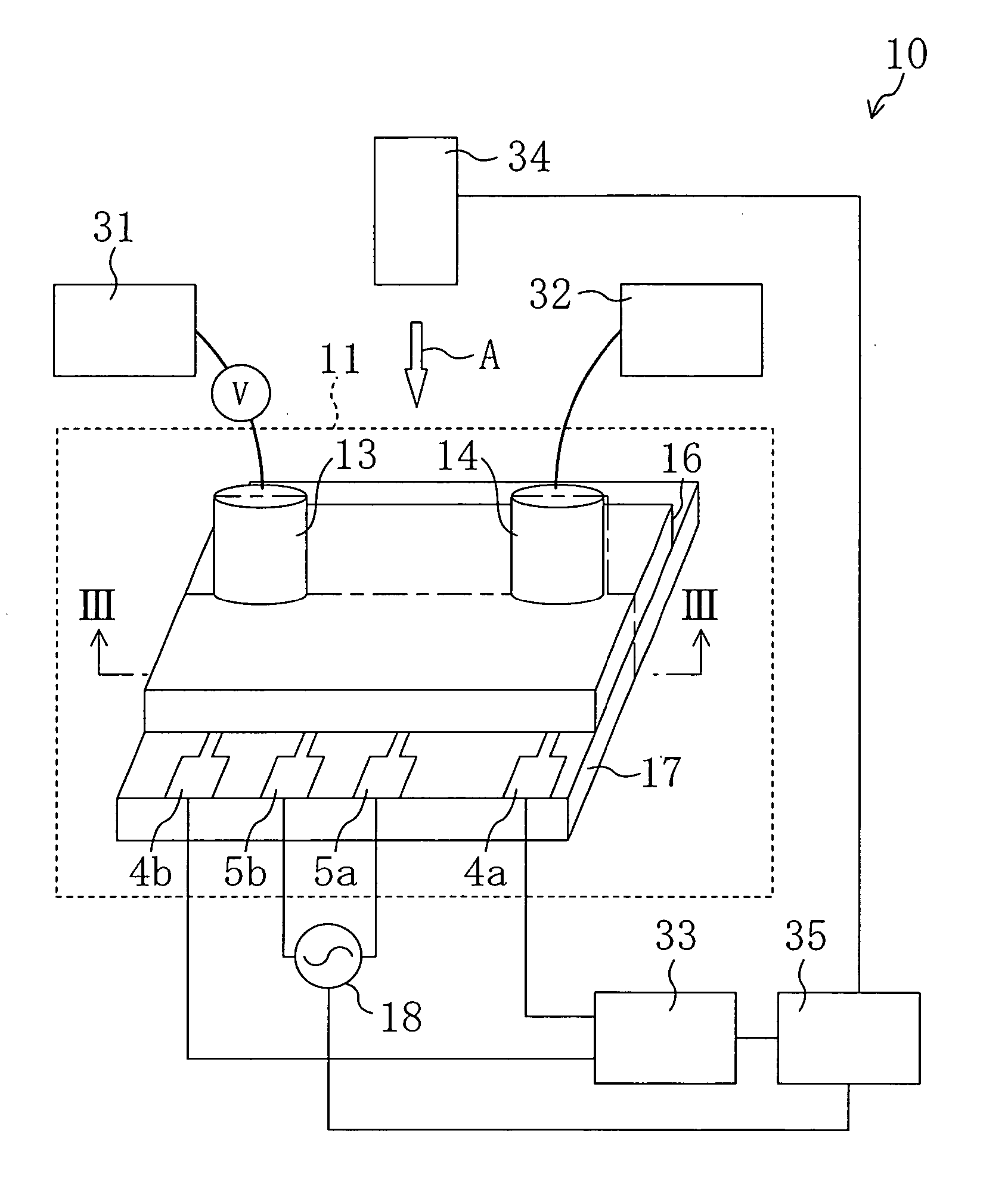
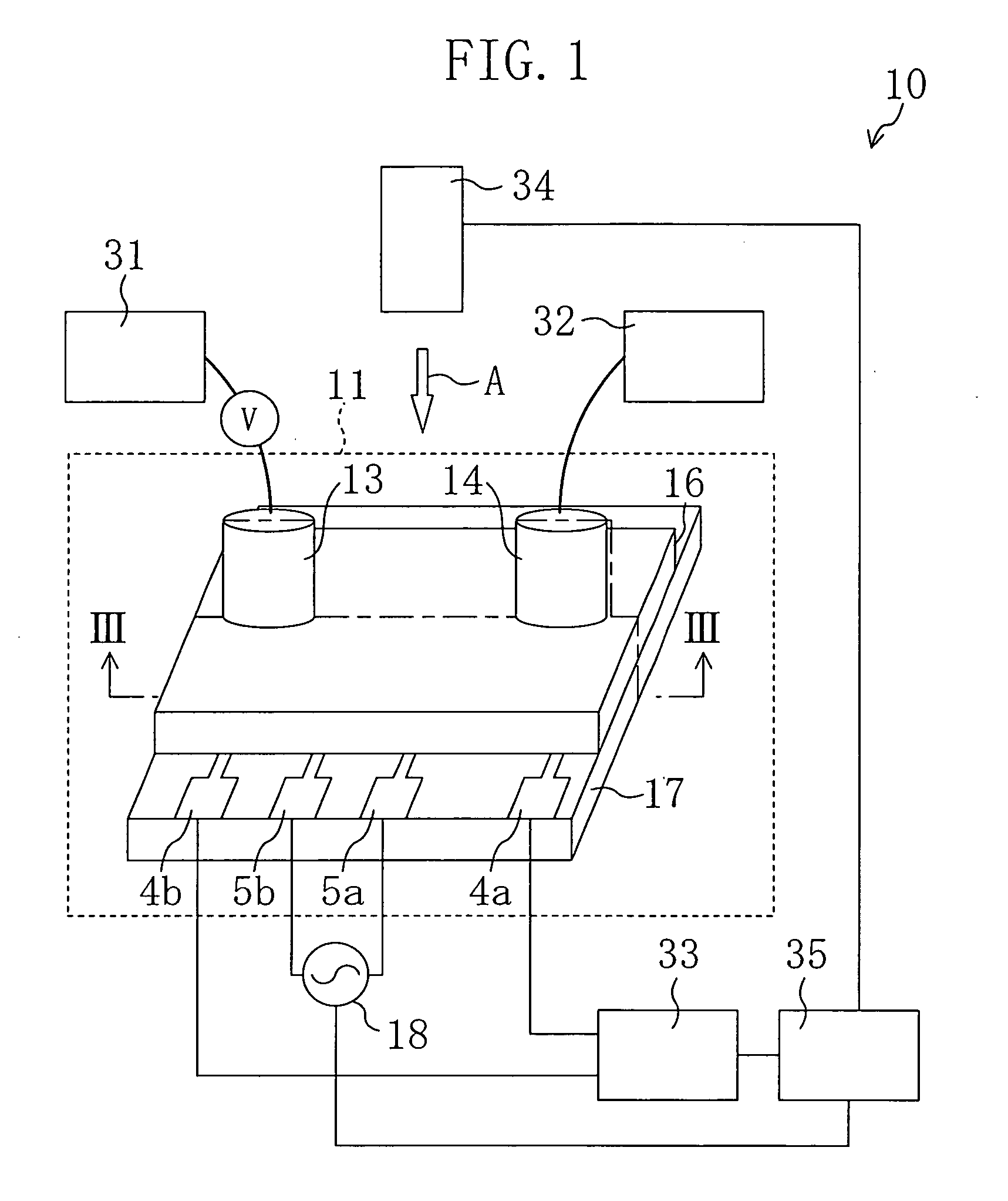
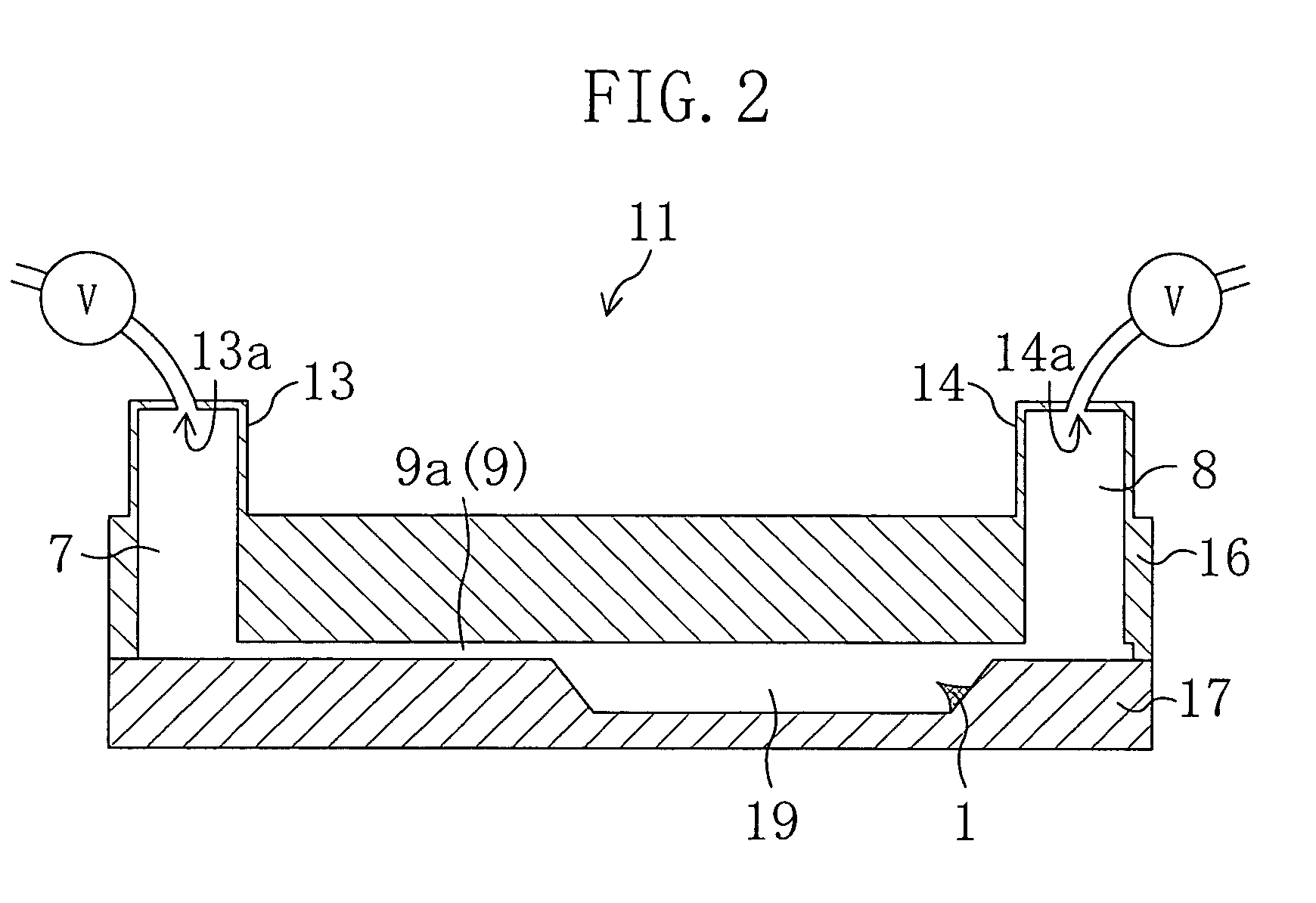
FIG. 1 is a diagram illustrating the structure of a measurement device according to this embodiment. FIG. 2 is a cross-sectional view taken along the line III-III of FIG. 1.
As shown in FIG. 1, a measurement device 10 according to this embodiment includes a measurement cell 11, a current application section 18, pumps 31 and 32, a measuring section 33, an imaging section 34, and a calculator 35.
The measurement cell 11 includes a substrate 17, a substrate 16 provided on the substrate 17. The substrates 16 and 17 are bonded to each other. As shown in FIG. 1, terminals 4a, 4b, 5a and 5b are provided on the substrate 17.
The current application section 18 is, as shown in FIG. 1, electrically connected to the terminals 5a and 5b provided on the substrate 17.
The pumps 31 and 32 are, as shown in FIG. 1, connected to opening portions 13a and 14a formed in an inlet connector 13 and an outlet connector 14, respectively.
The measuring section 33 is connected to the terminals 4a and 4b, a...
embodiment 2
In this embodiment, a measurement cell 11′ which can be used instead of the measurement cell 11 in the measurement device 10 of EMBODIMENT 1 will be described with reference to the accompanying drawings. Note that each member also shown in EMBODIMENT 1 is identified by the same reference numeral for the purpose of simplicity.
The measurement cell 11′ of this embodiment has substantially the same appearance as that of the measurement cell 11 of EMBODIMENT 1. Thus, in this embodiment, a case where the measurement cell 11 is replaced by the measurement cell 11′ will be described.
FIG. 7 is a cross-sectional view taken along the line III-III of FIG. 1. FIG. 8 is a perspective view of the measurement cell 11′ seen from the arrow A of FIG. 1. Note that a cross-sectional view taken along the line III-III of FIG. 8 corresponds to the cross-sectional view of FIG. 7. Moreover, in FIG. 8, the substrate 16 of the measurement cell 11′ is omitted.
The measurement cell 11′ has substantially the...
embodiment 3
FIG. 9 is a diagram illustrating the structure of a measurement device of this embodiment.
As shown in FIG. 9, the measurement device 10′ of this embodiment includes the measurement cell 11 or the measurement cell 11′, as the measurement device 10 of EMBODIMENT 1 or EMBODIMENT 2. More specifically, in the measurement device 10′ of this embodiment, the measurement cell 11 or the measurement cell 11′ is provided plural in number. The plurality of measurement cells 11 or 11′ are integrated in a matrix pattern. The structure of the measurement cell 11 or 11′ is exactly the same as that of EMBODIMENT 1 or EMBODIMENT 2.
Inlet connectors 13 and outlet connectors 14 provided in each of the plurality of measurement cells 11 or 11′ are connected to flow pass switchers 38 each including a valve and a pump. A structure is used in which the inlet connectors 13 and the outlet connectors 14 are made to be interchangeably used as outlets and as inlets by the flow pass switcher 38.
Furthermore, i...
PUM
| Property | Measurement | Unit |
|---|---|---|
| diameter | aaaaa | aaaaa |
| electric | aaaaa | aaaaa |
| resistance | aaaaa | aaaaa |
Abstract
Description
Claims
Application Information
 - R&D
- Intellectual Property
- Life Sciences
- Materials
- Tech Scout
- Unparalleled Data Quality
- Higher Quality Content
- 60% Fewer Hallucinations
Browse by: Latest US Patents, China's latest patents, Technical Efficacy Thesaurus, Application Domain, Technology Topic, Popular Technical Reports.
© 2025 PatSnap. All rights reserved.Legal|Privacy policy|Modern Slavery Act Transparency Statement|Sitemap|About US| Contact US: help@patsnap.com


