Molded electronic assembly

a technology of electronic assembly and molded body, which is applied in the direction of electrical apparatus casing/cabinet/drawer, coupling device connection, insulated conductor, etc., can solve the problems of large variability in products, high cost, and heavy weight of wiring integration assemblies, and achieves less volume, less weight and cost. , the effect of fewer parts

Active Publication Date: 2008-12-09
BELL HELICOPTER TEXTRON INC
View PDF13 Cites 6 Cited by
  • Summary
  • Abstract
  • Description
  • Claims
  • Application Information

AI Technical Summary

Benefits of technology

[0008]The present invention provides a molded electronic assembly. The molded electronic assembly of the present invention includes a wiring harness with connectors connected thereto, and a molded body formed to encapsulate the wiring harness and provide access to the connectors. The molded may comprise a plastic material such as polyurethane or other moldable material. A conductive coating may be placed on the outer surface of the molded body to provide electrical shielding. Additionally, the wiring harness may be shielded with a wrapping of metallic tape or the like. The molded electronic assembly of the present invention may include a grounding fixture or grommet that provides mechanical properties of a structural fixture and allows for ground wires to be terminated. The molded electronic assembly of the present invention has fewer parts and less volume, weighs and costs less, is more reliable and has less environmental susceptibility than the wiring integration assemblies of the prior art.

Problems solved by technology

Wiring integration assemblies tend to be expensive, heavy, bulky, and subject to environmental constraints.
Welded and brazed chassis construction involve many details, with expensive recurring process, and provide considerable variability in products.
Cast chassis are expensive to make and have poor material properties.
Thick walls lead to more material expense and weight.
All of these parts increase the cost, weight and complexity of the integrated wiring assemblies.
All of these environmental contaminates can result in corrosion, shorting and other problems.
Wiring integration assemblies in aircraft are also subject to vibrations.
In most cases, the internal wiring harnesses are unsupported in the chassis.
Vibration can lead to chafing and failure of wiring insulation, and loads and potential failure of wiring connections.

Method used


Image

  • Molded electronic assembly
  • Molded electronic assembly
  • Molded electronic assembly

Examples


Embodiment Construction

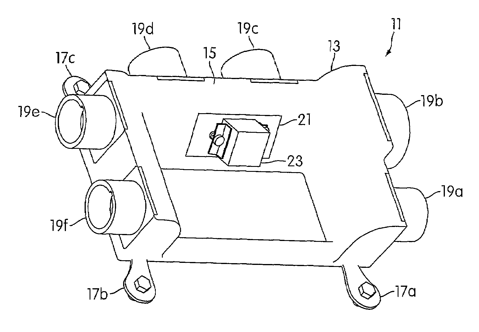
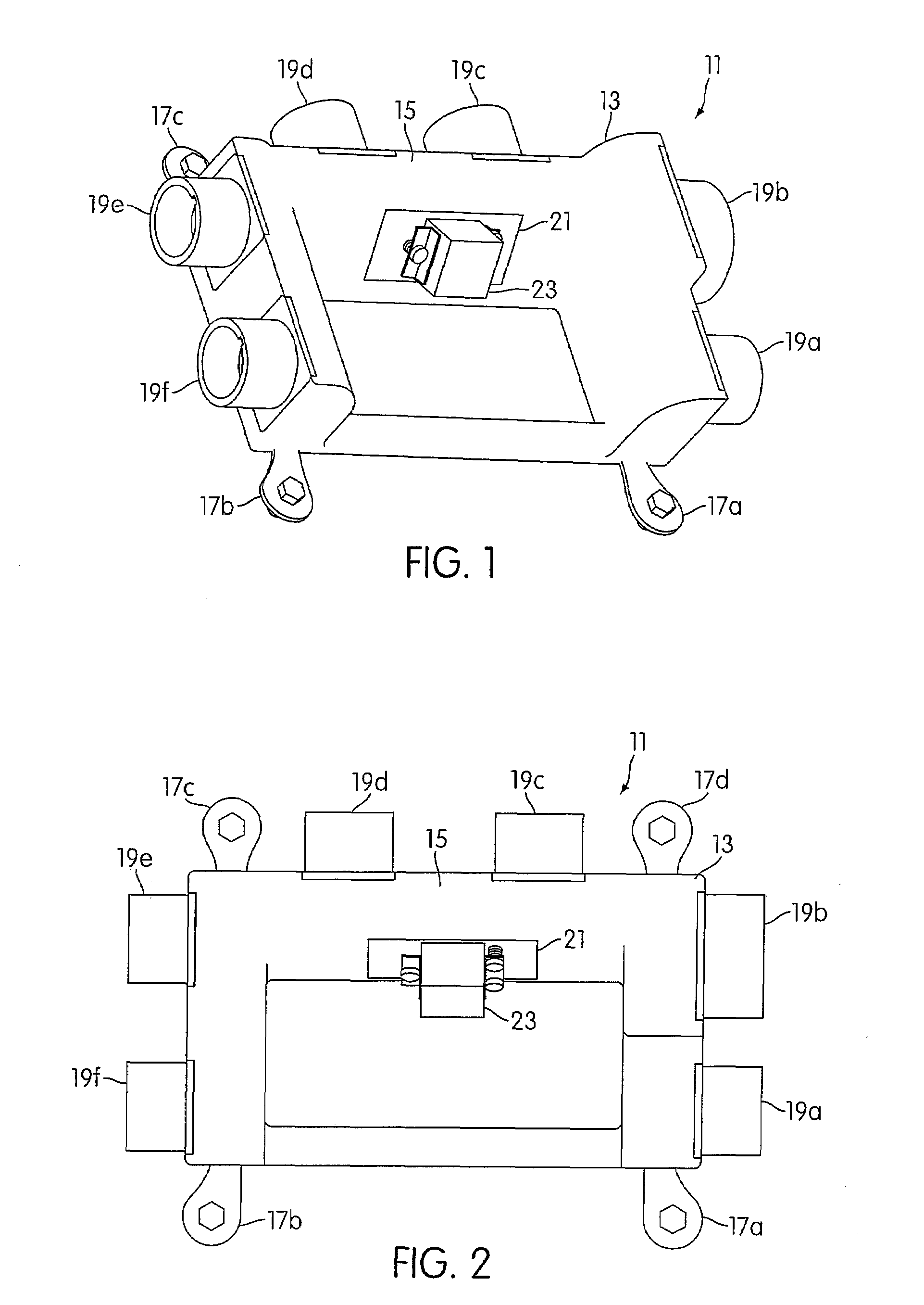
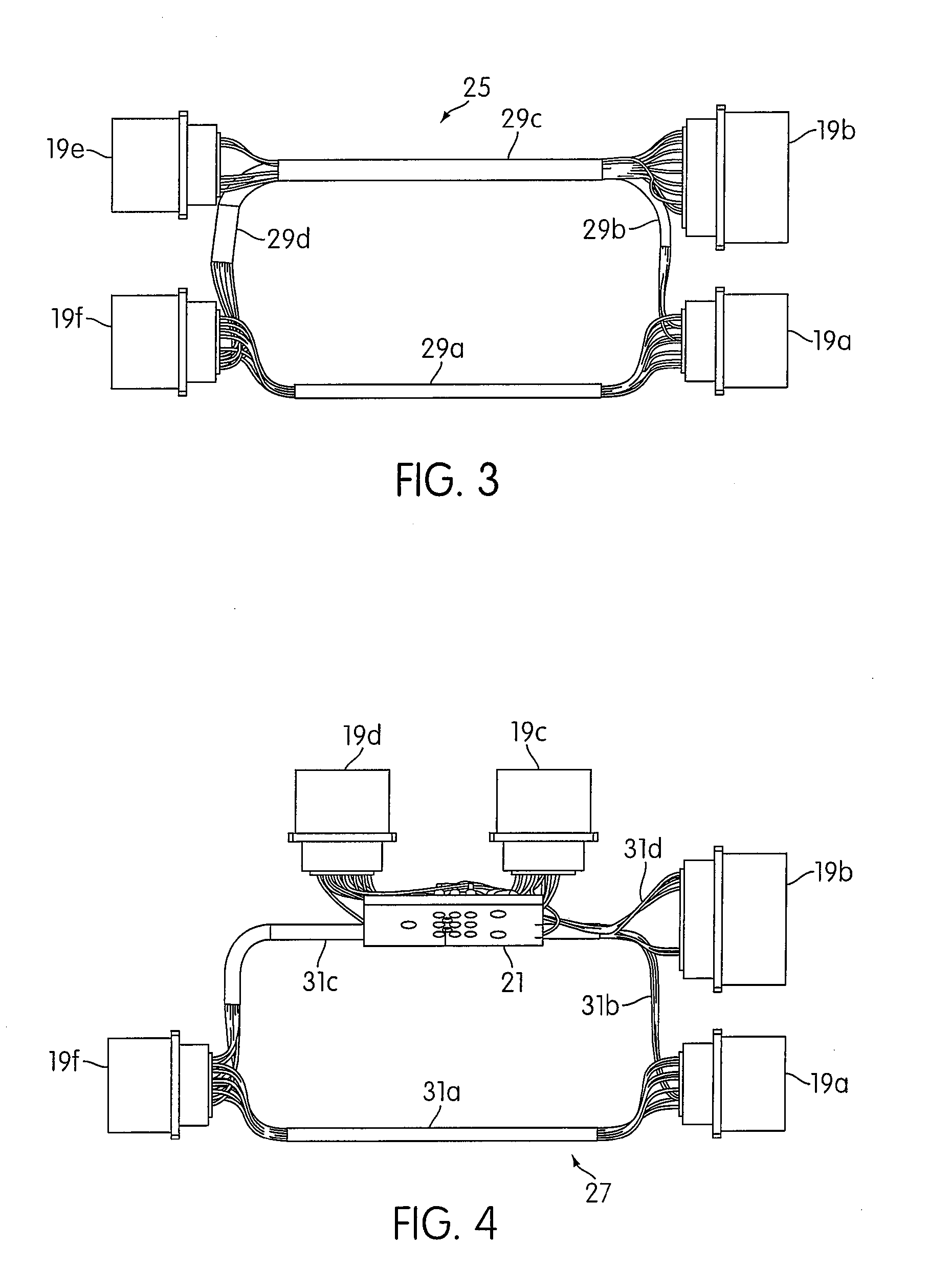
[0013]Referring now to the drawings, and first to FIGS. 1 and 2, a molded electronic assembly is designated generally by the numeral 11. Molded electronic assembly includes a molded body 13, which encapsulates one or more wiring harnesses (not shown in FIGS. 1 and 2) that will be described in detail with respect to FIGS. 3 and 4. Molded body 13 is formed from a moldable plastic material such as polyurethane. Other plastic materials such as Hexcell™, Hycor™, silicone or that like may be used to form molded body 13. The material of molded body 13 should have sufficient strength, hardness and other mechanical and electrical properties for use as a replacement for an aircraft integrated wiring assembly.

[0014]Molded body 13 may be covered with a conductive coating 15 to provide electrical shielding to the wiring harness or harnesses. A suitable conductive coating may be provided by a conductive paint, such a silver loaded composition. A conductive coating may also be provided by a metall...


PUM


Abstract

A molded electronic assembly of the present invention includes a wiring harness with connectors connected thereto, and a molded body formed to encapsulate the wiring harness and provide access to the connectors. The molded may comprise a plastic material such as polyurethane or other moldable material. A conductive coating may be placed on the outer surface of the molded body to provide electrical shielding. Additionally, the wiring harness may be shielded with a wrapping of metallic tape or the like. The molded electronic assembly of the present invention may include a grounding fixture or grommet that provides mechanical properties of a structural fixture and allows for ground wires to be terminated.

Description

CROSS-REFERENCE TO RELATED APPLICATION[0001]The present application claims the benefit of Provisional Application No. 60 / 441,140, filed Jan. 17, 2003, and titled MOLDED ELECTRONIC ASSEMBLY.FIELD OF THE INVENTION[0002]The present invention relates generally to the field of electrical wiring assemblies, and more particularly to a molded electronic assembly for electrically interconnecting devices and wiring and bus systems in aircraft.DESCRIPTION OF THE PRIOR ART[0003]Currently, aircraft wiring and bus systems are implemented in integrated wiring systems. Integrated wiring systems include wiring harnesses and integrated wiring assemblies. Integrated wiring assemblies are used to interconnect wiring harnesses and to connect devices to the wiring harnesses.[0004]A wiring integration assembly includes a metal chassis, typically of welded, brazed or cast construction, having one or more wiring harnesses disposed therein. Connectors are affixed to the chassis to provide connections to the ...

Claims


Application Information

Patent Timeline
Patent Type & Authority Patents(United States)
IPC IPC(8): H02G3/04H05K5/00
CPCH05K5/0034
Inventor MARSH, CHARLES W.FRISSORA, JOSEPH R.
Owner BELL HELICOPTER TEXTRON INC
Why Eureka
Try Eureka