UV transmittance measuring device

a transmittance measuring and uv technology, applied in the direction of calibration apparatus, optical radiation measurement, instruments, etc., can solve the problems of low cost design, low accuracy, and large errors, and achieve the effect of efficient and accurate measurement, computation and display

Active Publication Date: 2008-12-09
002134761 ONTARIO
View PDF16 Cites 3 Cited by
  • Summary
  • Abstract
  • Description
  • Claims
  • Application Information

AI Technical Summary

Benefits of technology

[0015]The present invention provides a small, compact device that efficiently and accurately measures, computes and displays the ultraviolet transmittance / ultraviolet absorbance (UVT / UVA) of water samples. The device disclosed herein is used to measure the UVT / UVA of water samples while compensating for lamp drift and fluctuations, using only one light detector, and without the need for expensive optical components such as mirrors and / or quartz lenses.
[0016]The present invention is invaluable for companies that design, sell and / or service UV water and wastewater disinfection systems. Since natural organic matter (NOM) in water has strong absorption properties to UV light at the 254 nm wavelength, the invention has many applications in the water and wastewater industry which require the measurement of NOM. Such applications include filtration, coagulation, chlorination, ozone and ion exchange treatment methods, as well as water and wastewater treatment plant efficiency and effectiveness.
[0017]The device disclosed herein can also help predict the potential formation of disinfection by-products (DBP's) formed by the reaction of chlorine and dissolved organics within a water or wastewater treatment system. This relates to the determination of the Specific UV Absorbance (SUVA) of a water sample, designated by the Environmental Protection Agency (EPA) as an important water quality parameter.

Problems solved by technology

One of the main difficulties when designing UVT instrumentation is due to the nature of UV light sources.
The most common UV light source is the mercury lamp, which has a tendency to drift and fluctuate causing significant errors in the UVT measurements when using the single-beam method described above.
Such fluctuation and drift is very common in UV lamps and is due primarily to changes in temperature and imperfections in the ballast and lamp.
Some low cost designs make no attempt to compensate for such fluctuations and drift which severely reduces accuracy.
However, significant errors are still common.
However, this is very costly to implement since additional electronics, a second sensor and a proportionally adjustable ballast is required to power the UV lamp.
However, this method introduces new errors due to the use of two sensors.
Also, if each sensor is looking at a different part of the lamp and / or looking at the lamp from a different angle, errors can occur since the UV lamp output varies not only over time, but also over the surface of the lamp.
For these reasons, this particular design is not very common.
However, there are still errors present in this method that are not present in the single-beam method.
Since two sample vials are required, one for the test sample and one for the blank sample, significant errors can occur since the two sample vials are not necessarily matched.
Also, this system is expensive due to use of a switchable beam splitting apparatus and the potential use of precision manufacturing to attempt to match the optics of the two beam paths.
It should also be noted that the cost of such optical apparatus becomes especially expensive when using UV light since UV light does not readily transmit through glass lenses making the use a quartz optical components necessary.
UV light also has a tendency to erode reflective surfaces, making the use of mirrors undesirable.
However, this method is still susceptible to errors caused by using the two separate light paths and light detectors, as discussed above.

Method used


Image

  • UV transmittance measuring device
  • UV transmittance measuring device
  • UV transmittance measuring device

Examples


Embodiment Construction

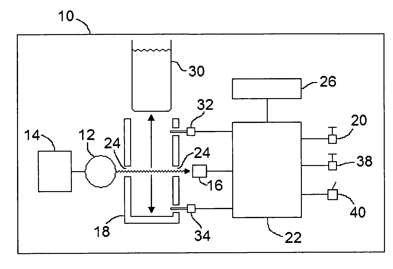
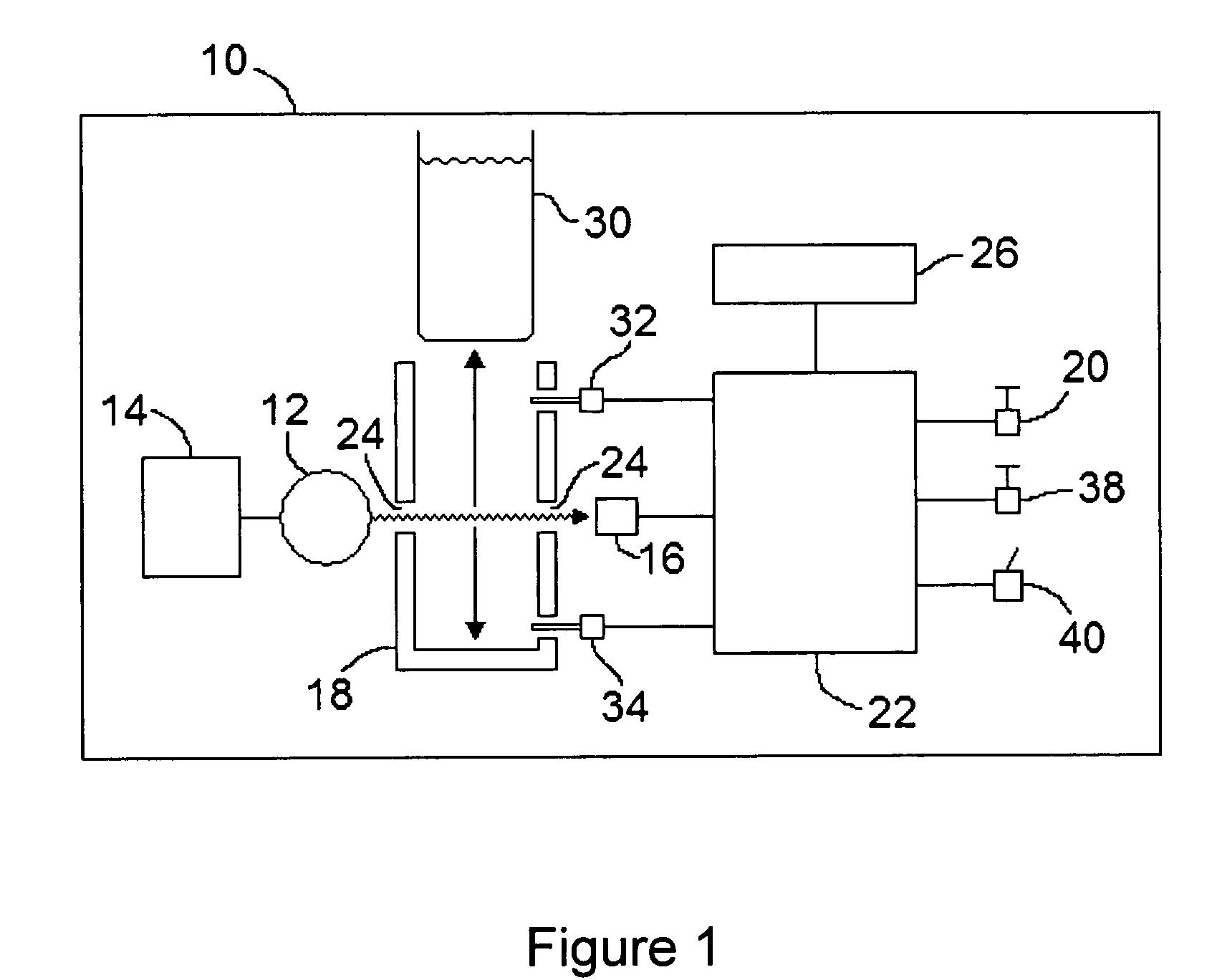
[0040]Referring to FIG. 1, a UV transmittance measuring device constructed in accordance with the present invention is shown generally at 10 and includes a single UV lamp 12 powered by a UV lamp ballast 14.

[0041]Lamp 12 can be any UV light source that emits light of a wavelength that can be absorbed by organic matter, generally between 250-290 nm range UV. Lamp 12 can be a mercury lamp, deuterium lamp or a deep UV LED light source. In a preferred embodiment, lamp 12 may be a mercury low pressure UV lamp emitting radiation with a wavelength of 254 nm as the UV source.

[0042]A sample vial holder 18 holds a sample vial 30 used to hold the liquid sample being tested. Sample vial holder 18 may be made of a material which is not degraded over time by exposure to UV light and for this reason a metal such as aluminum is preferred and if a metal is used apertures 24 are required on opposed faces of the sample vial holder 18 to provide a path for the UV light through the holder. Apertures 24 a...


PUM

PropertyMeasurementUnit
path lengthaaaaaaaaaa
wavelengthaaaaaaaaaa

Abstract

A device to measure the amount of ultraviolet (UV) light transmitted through a water sample, relative to the amount of UV light transmitted through a sample of known UV transmittance, known as UV percent transmittance (UVT). A single UV sensor is used to measure the amount of UV light transmitted through the blank sample and through the water sample under test. In order to maintain accuracy, compensation must be made for fluctuations or drift in the UV lamp output which is common in UV lamps and due primarily to changes in temperature and imperfections in the lamp. The UV sensor measures the amount of light being emitted by the lamp at the times before and / or after the UV sensor measures the amount of UV light transmitted through the blank and water samples. A microprocessor computes the UVT while using the detector readings to compensate the calculated UVT for any drift and fluctuations in the UV lamp output.

Description

CROSS REFERENCE TO RELATED U.S. PATENT APPLICATIONS[0001]This patent application relates to U.S. utility patent application Ser. No. 60 / 691,803 filed on Jun. 20, 2005, entitled UV TRANSMITTANCE MEASURING DEVICE, filed in English, which is incorporated herein in its entirety by reference.FIELD OF THE INVENTION[0002]The present invention is related to an apparatus for measuring water quality and particularly relates to several applications within the water and wastewater treatment industry.BACKGROUND OF THE INVENTION[0003]Rapid and reliable measurement of water quality is of major importance, particularly with respect to drinking water. Ultraviolet transmittance (UVT) is a measure of the transmittance of water to UV light. Fundamentally, this requires a UV light source to shine UV light through a water sample and into a UV detector. The UVT of a water sample is calculated as the amount of UV light that passes through the water sample under test (test sample) divided by the amount of l...

Claims


Application Information

Patent Timeline
Patent Type & Authority Patents(United States)
IPC IPC(8): G01N21/33
CPCG01N21/274G01N21/276G01N21/33
Inventor GLOVER, JAMES ANDREW
Owner 002134761 ONTARIO
Why Eureka
Try Eureka