
Power system

a power system and power technology, applied in the direction of machines/engines, engine starters, transportation and packaging, etc., can solve the problems of large and expensive motor/generator of '904 patent, electric machine of '904 patent may not have a control system that allows

Inactive Publication Date: 2008-12-09
CE COMPOSITES BASEBALL +1
View PDF9 Cites 28 Cited by
  • Summary
  • Abstract
  • Description
  • Claims
  • Application Information

AI Technical Summary

Problems solved by technology

Although the electric machine of the '904 patent may be used to start an internal combustion engine, the motor / generator of the '904 patent may be large and expensive.
In addition, the electric machine of the '904 patent may not have a control system that allows for efficient operation of the motor / generator during a starting sequence.

Method used


Image

  • Power system
  • Power system
  • Power system

Examples


Embodiment Construction

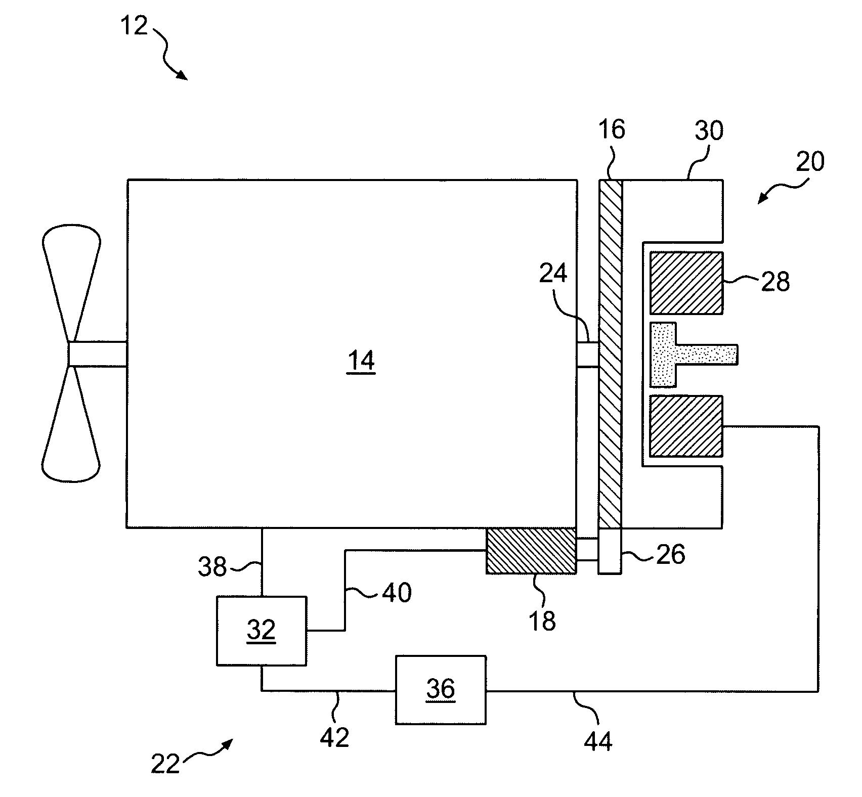
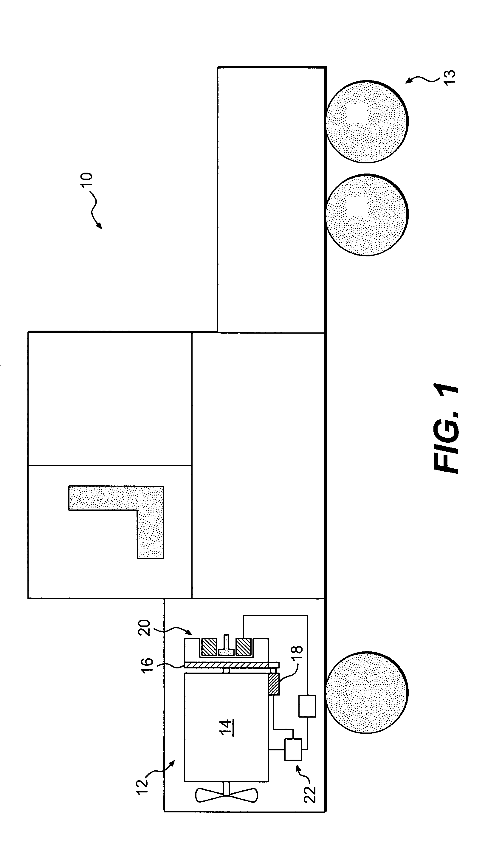
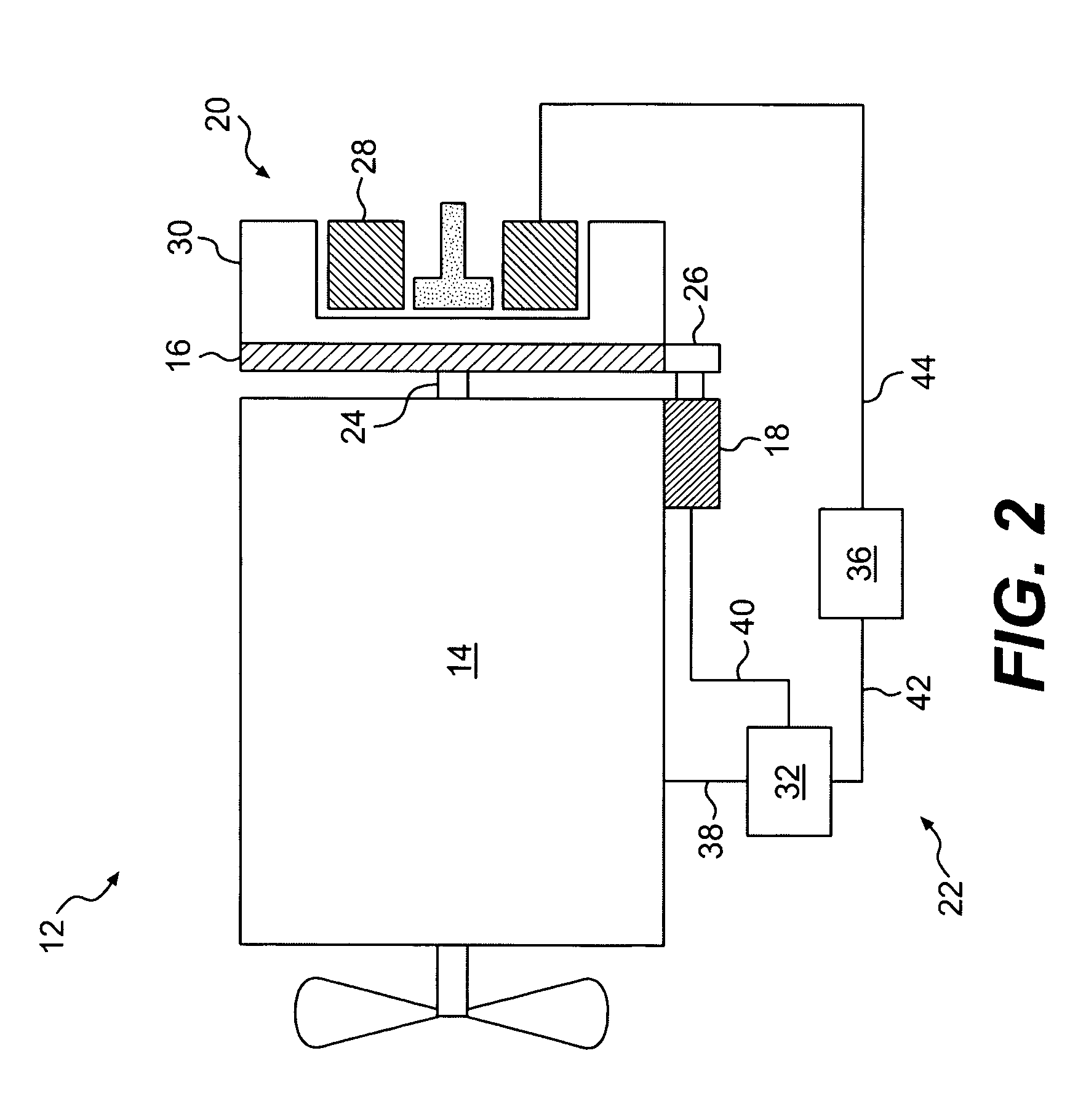
[0012]FIG. 1 illustrates a work machine 10 having an exemplary embodiment of a power system 12 and a traction device 13. Power system 12 may include an engine 14 having a flywheel 16, a starter 18, a motor / generator 20, and a control system 22.

[0013]As illustrated in FIG. 2, flywheel 16 may be connected to engine 14. For example, flywheel 16 may be connected to a crankshaft 24 of engine 14, or in any other manner known in the art. Flywheel 16 may be any type of device for storing and releasing rotational energy to dampen transient loads placed on or exerted by engine 14. For example, flywheel 16 may be a fixed inertia flywheel, a variable inertia flywheel, an electric flywheel, or any other flywheel known in the art. In addition, the flywheel may include multiple rotating masses. It is also contemplated that flywheel 16 may be absent from engine 14 and that motor / generator 20 may act as a means for storing and releasing rotational inertia.

[0014]Starter 18 may be connected to engine ...


PUM


Abstract

A power system includes an engine, a motor / generator operatively connected to the engine, and a starter operatively connected to at least one of the engine and the motor / generator.

Description

U.S. GOVVERNMENT RIGHTS[0001]This invention was made with government support under the terms of Contract No. DE-F004-2000AL6701 7 awarded by the Department of Energy. The government may have certain rights in this invention.TECHNICAL FIELD[0002]The present invention relates generally to a power system, and more particularly to a power system having a starter and a motor / generator.BACKGROUND[0003]Work machines, including on-highway vehicles, have an engine for powering the work machine. The engine may be a diesel engine, a gasoline engine, a natural gas engine, or any other type of engine known in the art. The engine produces torque to power the work machine, and likewise requires torque to start the engine.[0004]The torque required to start the engine may be generated with a starting system. For example, U.S. Pat. No. 5,773,904 (the '904 patent) issued to Schiebold et al. on Jun. 30, 1998, describes an electric machine used to start an internal combustion engine. The electric machin...

Claims


Application Information

Patent Timeline
Patent Type & Authority Patents(United States)
IPC IPC(8): H02K47/04F02N11/04F02N15/00H02K7/02
CPCB60K6/485F02N11/04B60L2240/421B60L2240/441B60W2510/0638B60W2710/081Y02T10/6226Y02T10/642F02N11/006F02N2200/022F02N2300/2002Y02T10/62Y02T10/64B60K2006/268
Inventor HOFF, BRIAN D.ALGRAIN, MARCELO C.
Owner CE COMPOSITES BASEBALL
Learn More