
Hybrid battery module with a voltage balancing unit and its charging and discharging method

a hybrid battery and voltage balancing technology, which is applied in the direction of battery arrangement, transportation and packaging, and several simultaneous batteries, etc., can solve the problems of easy damage to the battery module, longer charging/discharging time, and lower load capacity, so as to achieve flexibility in design

Inactive Publication Date: 2008-12-09
COMPAL ELECTRONICS INC
View PDF2 Cites 26 Cited by
  • Summary
  • Abstract
  • Description
  • Claims
  • Application Information

AI Technical Summary

Benefits of technology

The present invention provides a hybrid battery module with a voltage balancing unit and its charging and discharging method. The module contains multiple cell sets that can be selected for different sizes of electronic devices, providing more design flexibility. The charging and discharging operations are performed in parallel, resulting in higher load capacity and shorter charging time. The module includes a controller and a voltage balancing unit to detect and control the voltage and temperature of the cell sets. The method allows for the simultaneous discharging of the cell sets, ensuring a balanced state of energy. The technical effects of the invention include higher flexibility, improved performance, and efficient energy utilization.

Problems solved by technology

However, once one of the cells encounters a problem during the charging / discharging operation, the forgoing patent is not able to turn off the battery charging switches simultaneously, which easily damages the battery module.
Additionally, the cell sets of the forgoing patent are charged and discharged in series, thus its disadvantages are lower load capacity and longer charging / discharging time.

Method used


Image

  • Hybrid battery module with a voltage balancing unit and its charging and discharging method
  • Hybrid battery module with a voltage balancing unit and its charging and discharging method
  • Hybrid battery module with a voltage balancing unit and its charging and discharging method

Examples


Embodiment Construction

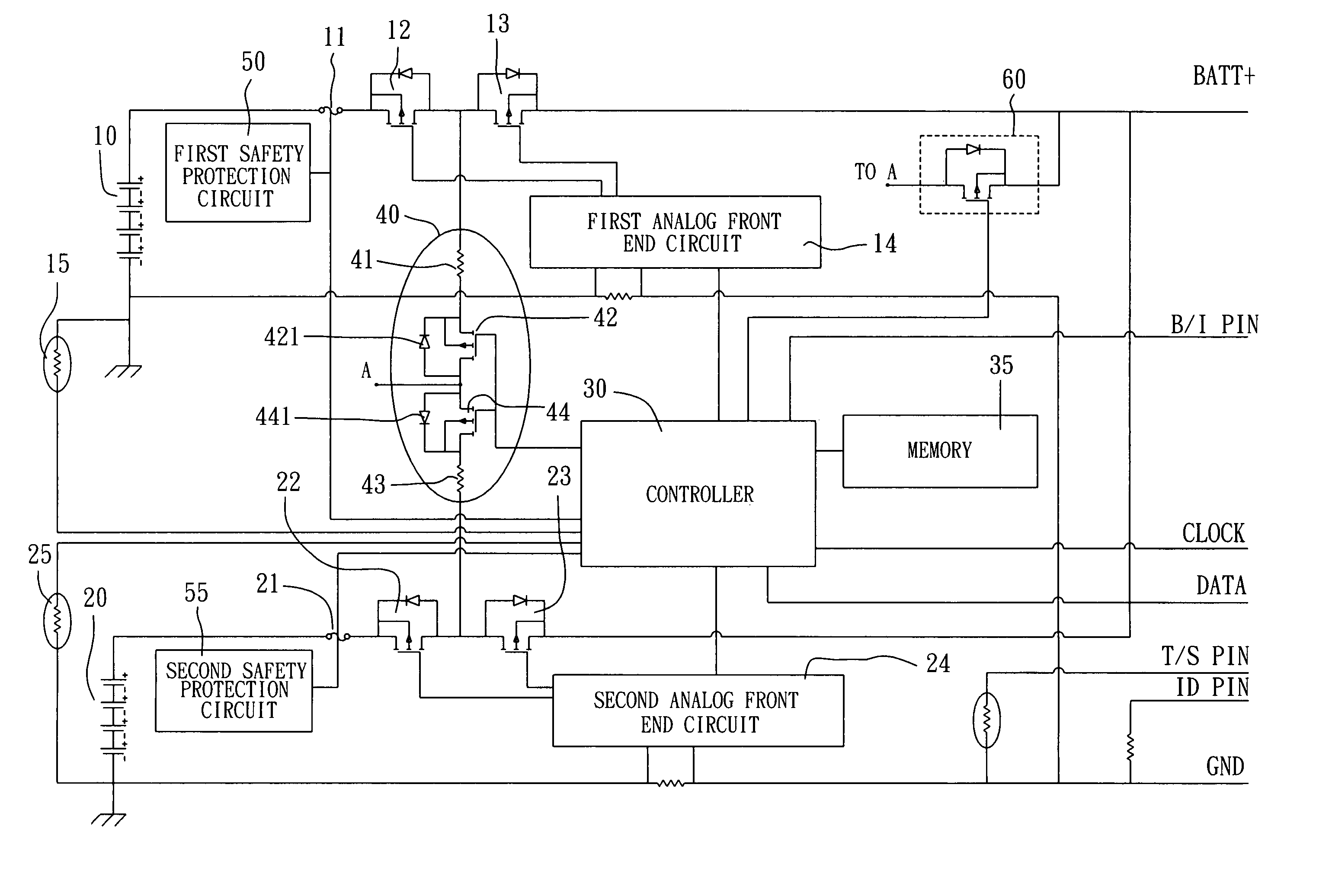
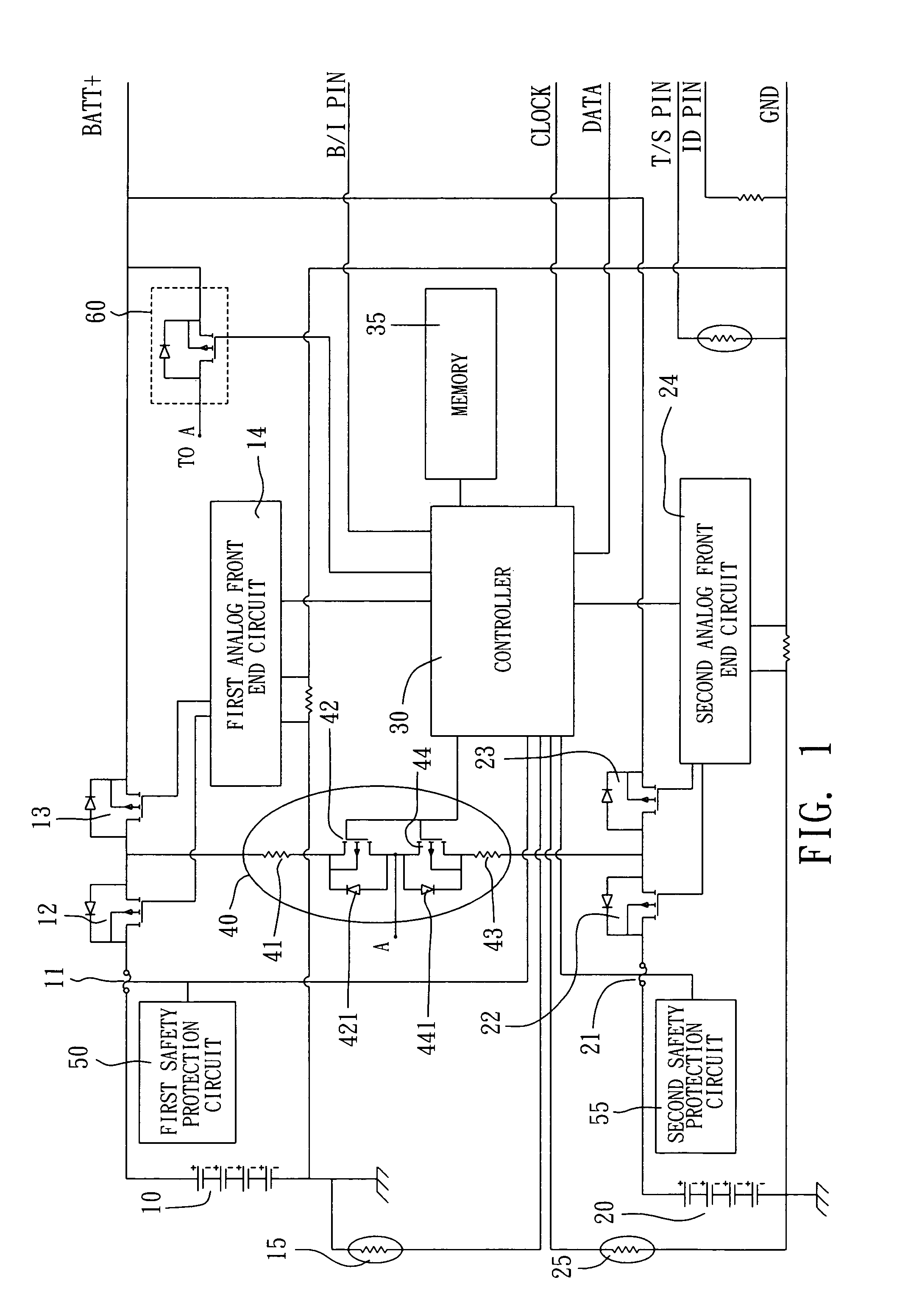
[0018]FIG. 1 is a schematic block diagram showing a hybrid battery module with a voltage balancing unit according to a preferred embodiment of the present invention. The hybrid battery module with a voltage balancing unit of the present invention at least comprises: a first cell set 10; a first programmable fuse 11; a first discharging switch 12; a first charging switch 13; a first analog front end circuit 14; a first thermister 15; a second cell set 20; a second programmable fuse 21; a second discharging switch 22; a second charging switch 23; a second analog front end circuit 24; a second thermister 25; a controller 30; and a voltage balancing unit 40.

[0019]Wherein, the first cell set 10 is a chargeable battery pack that comprises a plurality of cells.

[0020]The first programmable fuse 11 has three terminals, wherein a first end is coupled to the first cell set 10, a second end is coupled to a source of the first discharging switch 12, and a control terminal is coupled to the contr...


PUM


Abstract

The present invention relates to a hybrid battery module with voltage balancing unit, which comprises: a first cell set; a first programmable fuse; a first discharging switch; a first charging switch; a first analog front end circuit; a first thermister; a second cell set; a second programmable fuse; a second discharging switch; a second charging switch; a second analog front end circuit; a second thermister; a controller; and a voltage balancing unit; whereby the voltage of the first cell set and the second cell set can reach a balance state by the voltage balancing unit; and during the charging process, the first charging switch and the second charging switch will simultaneously be turned off when it meets a safety event; and during the discharging process, the first programmable fuse and the second programmable fuse will simultaneously be burned off when it meets a critical safety event so as to prevent cell from being burned; Furthermore, the present invention also provides a method for charging and discharging a hybrid battery module with a voltage balancing unit.

Description

BACKGROUND OF THE INVENTION[0001]1. Field of the Invention[0002]The present invention relates to a hybrid battery module with a voltage balancing unit and its charging and discharging method; and more particularly to a hybrid battery module can be discharged by a voltage balancing unit so as to reach the goal of voltage balance, and no matter the hybrid battery module is in a charging mode or a discharging mode, once a cell set meets an abnormal or a critical safety event, the charging switch, the discharging switch and fuse of the two cell sets will simultaneously be turned off, so as to prevent the cell sets from being damaged.[0003]2. Description of the Related Art[0004]Regarding the conventional battery module and its charging and discharging method, such as a battery module with a plurality of cell sets disclosed in US patent Publication No. 20050116688 (US published patent application). The battery module is mainly used to prevent a single (or specific) cell from being decayed...

Claims


Application Information

Patent Timeline
Patent Type & Authority Patents(United States)
IPC IPC(8): H02J7/00H02J7/02
CPCH02J7/0016H01M10/4207Y02E60/10
Inventor CHANG, CHEN CHIATARNG, CHUANG CHIH
Owner COMPAL ELECTRONICS INC
Learn More