Ergonomic appliance handle
a technology of ergonomics and handles, applied in the field of handles, can solve the problems of affecting the ergonomics affecting the operation affecting the use of the canister vacuum, so as to achieve the effect of convenient and convenient operation of the vacuum
- Summary
- Abstract
- Description
- Claims
- Application Information
AI Technical Summary
Benefits of technology
Problems solved by technology
Method used
Image
Examples
first embodiment
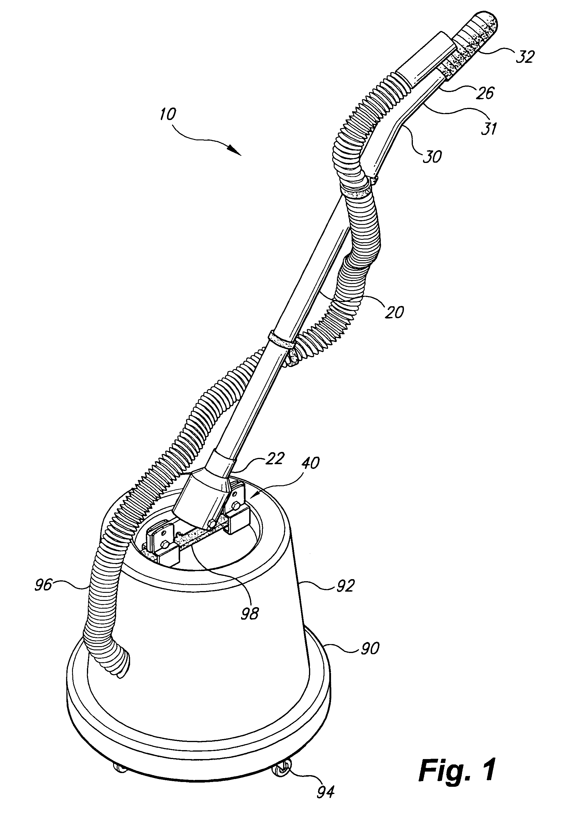
[0043]The present invention is an ergonomic appliance handle. Referring to FIG. 1, an ergonomic appliance handle 10 is shown attached to a carry handle 98 of a typical canister vacuum 90. The canister vacuum 90 illustrated is typical of a variety of vacuum cleaning appliances generally comprising a cylindrical housing 92 disposed vertically on a plurality of wheels 94, some or all of the wheels 94 being pivoting or caster type wheels. The housing 92 contains a motor and vacuum mechanism, and a collection receptacle. A proximal end of a flexible hose 96 is attached to an intake opening defined in the housing 92. At a distal end of the flexible hose 96, a cleaning attachment, accessory, or power nozzle, may be attached. A carry handle 98 is generally disposed atop the housing 92, the carry handle 98 lying generally horizontally as the canister vacuum 90 sits on a horizontal surface, such as a floor.
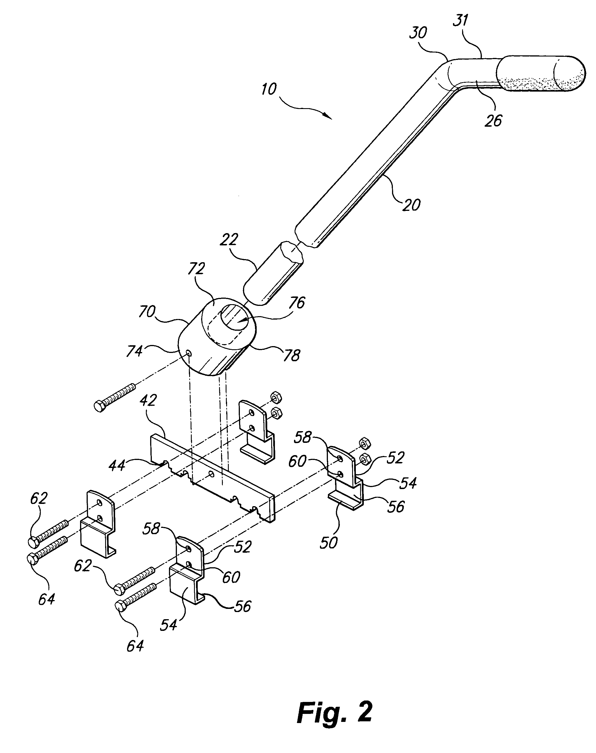
[0044]The ergonomic appliance handle 10 comprises an elongated shaft 20 having a proxim...
second embodiment
[0052]Turning now to FIG. 4, an ergonomic appliance handle 100 is shown attached to a carry handle 198 of a canister vacuum, the horizontal extent of the carry handle 198 being shorter than the carry handle 98 seen in FIG. 1. The ergonomic appliance handle 100 employs a mounting assembly 140 that is better suited to the shorter carry handle 198.
[0053]Referring to FIG. 5, the mounting assembly 140 of the second embodiment is shown in greater detail. A single pair of brackets 150 straddles the carry handle 198 and holds a coupling fixture 170 attached to the elongated shaft 20. Each of the brackets 150 has a flat upper portion 152 having an arcuate top edge 153. A bottom portion 154 of each bracket 150 is bent into a “C” shape defining a channel 156. An upper aperture 158, and at least one lower aperture 160 (two are shown) are defined in the upper portion 152 of each of the brackets 150. Each at least one lower aperture 160 receives a lower fastener 164 joining and clamping the two b...
third embodiment
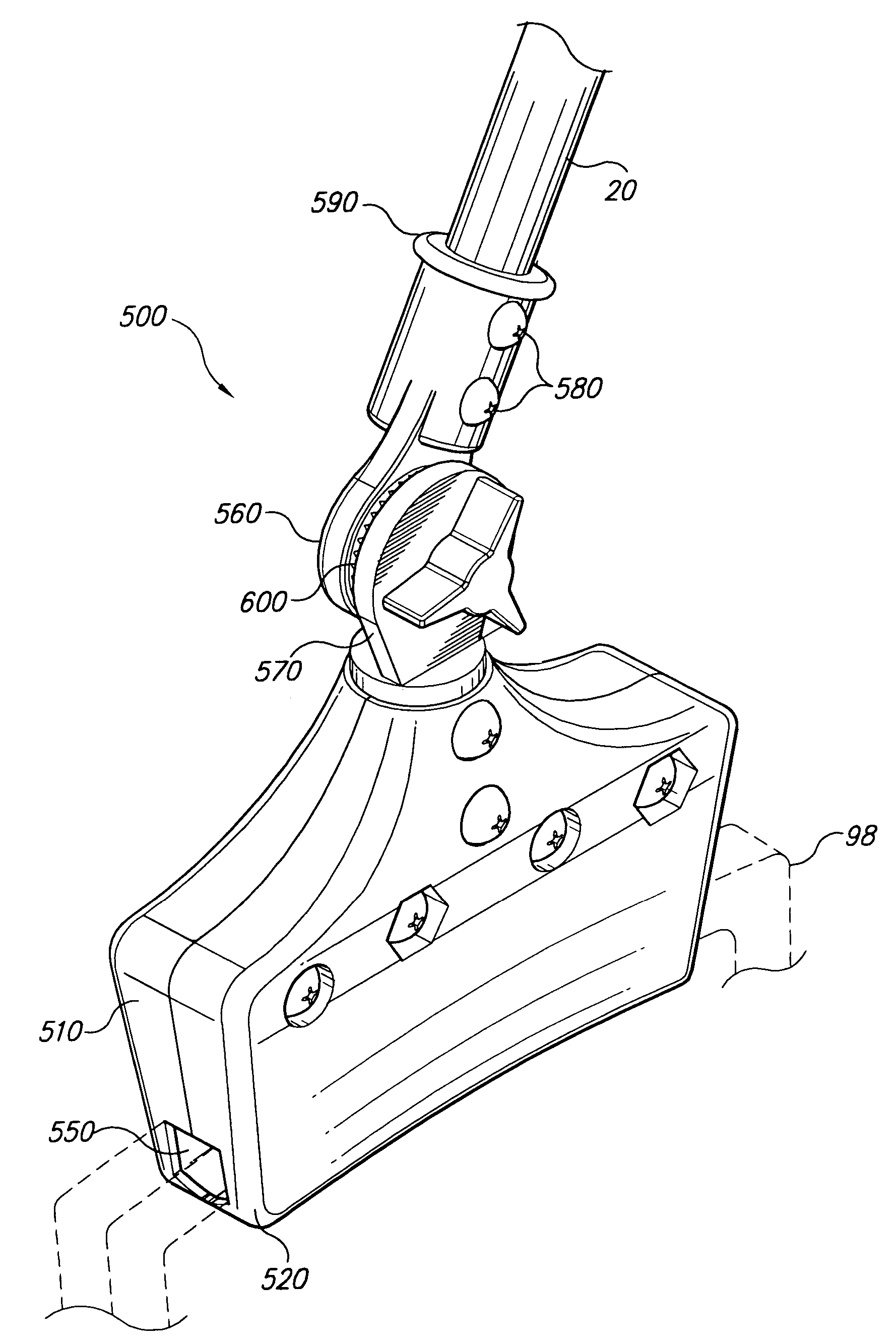
[0057]Turning now to FIGS. 8 and 9, an ergonomic appliance handle 400 is shown. The ergonomic appliance handle 400 employs a mounting assembly 440 that allows the angle of the elongated shaft 20 to be varied. The mounting assembly 440 illustrated employs brackets 50 to attach the mounting assembly 440 to the carry handle 98 of a canister vacuum. The brackets 50 support a crossbar 442, the crossbar 442 being similar to the crossbar 42 described above but somewhat wider. A coupling fixture 470 is supported on the crossbar 442.
[0058]The coupling fixture 470 is comprised of two members pivotally joined to one another. A base member 486, mounted to or formed as a unitary part of the crossbar 442, is pivotally joined to a socket member 472 that retains the elongated shaft 20. The socket member 472 has a socket end 474 wherein a cylindrical recess 476 is defined and adapted to receive the proximal end 22 of the elongated shaft 20. A mating portion 478 of the socket member 472 has a general...
PUM
 Abstract
Description
Claims
Application Information
 - R&D
- Intellectual Property
- Life Sciences
- Materials
- Tech Scout
- Unparalleled Data Quality
- Higher Quality Content
- 60% Fewer Hallucinations
Browse by: Latest US Patents, China's latest patents, Technical Efficacy Thesaurus, Application Domain, Technology Topic, Popular Technical Reports.
© 2025 PatSnap. All rights reserved.Legal|Privacy policy|Modern Slavery Act Transparency Statement|Sitemap|About US| Contact US: help@patsnap.com


