Method for operation of a power generation plant

a power generation machine and power technology, applied in the direction of electrical storage system, liquid degasification, separation process, etc., can solve the problem that the power component to be produced by the power generation machine is available only with a delay

Inactive Publication Date: 2008-12-16
GENERAL ELECTRIC TECH GMBH
View PDF24 Cites 43 Cited by
  • Summary
  • Abstract
  • Description
  • Claims
  • Application Information

AI Technical Summary

Benefits of technology

[0009]An initial operating state in which the maximum capability to suddenly increase the power for frequency support is available is an operating state in which all the power consuming machines in the power generation plant are being operated at maximum power. The entire power consumption of the power consuming machines—as will also be described in the following text quite possibly a multiple of the rating during equilibrium operation of the power generation plant—can in principle be made available to the grid simply by opening a switch. In a second step, although considerably more slowly, the power of the power generation machines can be increased, provided that they are not being operated at maximum power in the initial operating state. To this extent, it appears to be desirable to make use of an initial operating state in which the power consuming machines are running with their full power consumption, while the power generation machines are stationary or are running on no load. Admittedly, when seen in absolute terms, an initial operating state such as this results in the greatest potential to increase the power. However, the power component to be produced by the power generation machines is available only with a delay since power generation machines which are operated on no load—or to be more precise their generators—must first of all be synchronized to the grid. In the interest of the maximum power dynamic response, it has therefore been found to be advantageous to keep the power generation machines already synchronized to the grid with a small amount of power being emitted to the grid. In one very particularly preferred operating method, all of the power consuming machines are thus operated at at least 80% of their maximum power consumption. At the same time, all of the power generation machines are synchronized to the grid and are operated with as low a power output as possible, preferably of less than 10% or less than 20% of their maximum power output; however, operational reasons may also demand a higher minimum power. Starting from this initial operating state, it is possible when a rapid power demand occurs to shut down the power consuming machines by opening switches and at the same time to pass a command to increase the power to the power generation machines. The power which was previously consumed by the power consuming machines is then instantaneously available to the grid, and the power from the power generation machines is made available with a delay time that is intrinsic to the system and, in particular, with a power gradient that has an upper limit, but without having to previously wait for synchronization. The power dynamic response is thus maximized.
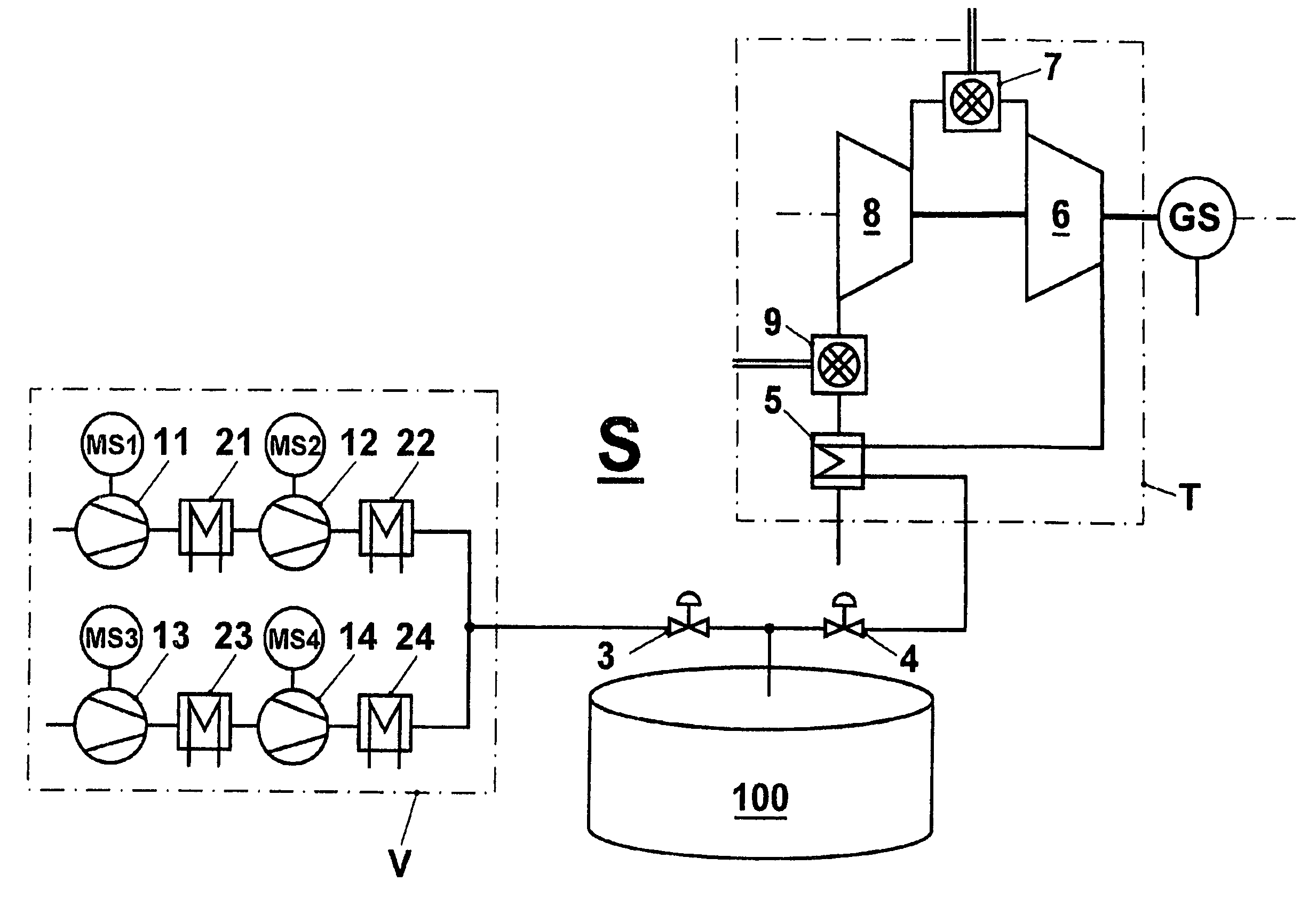
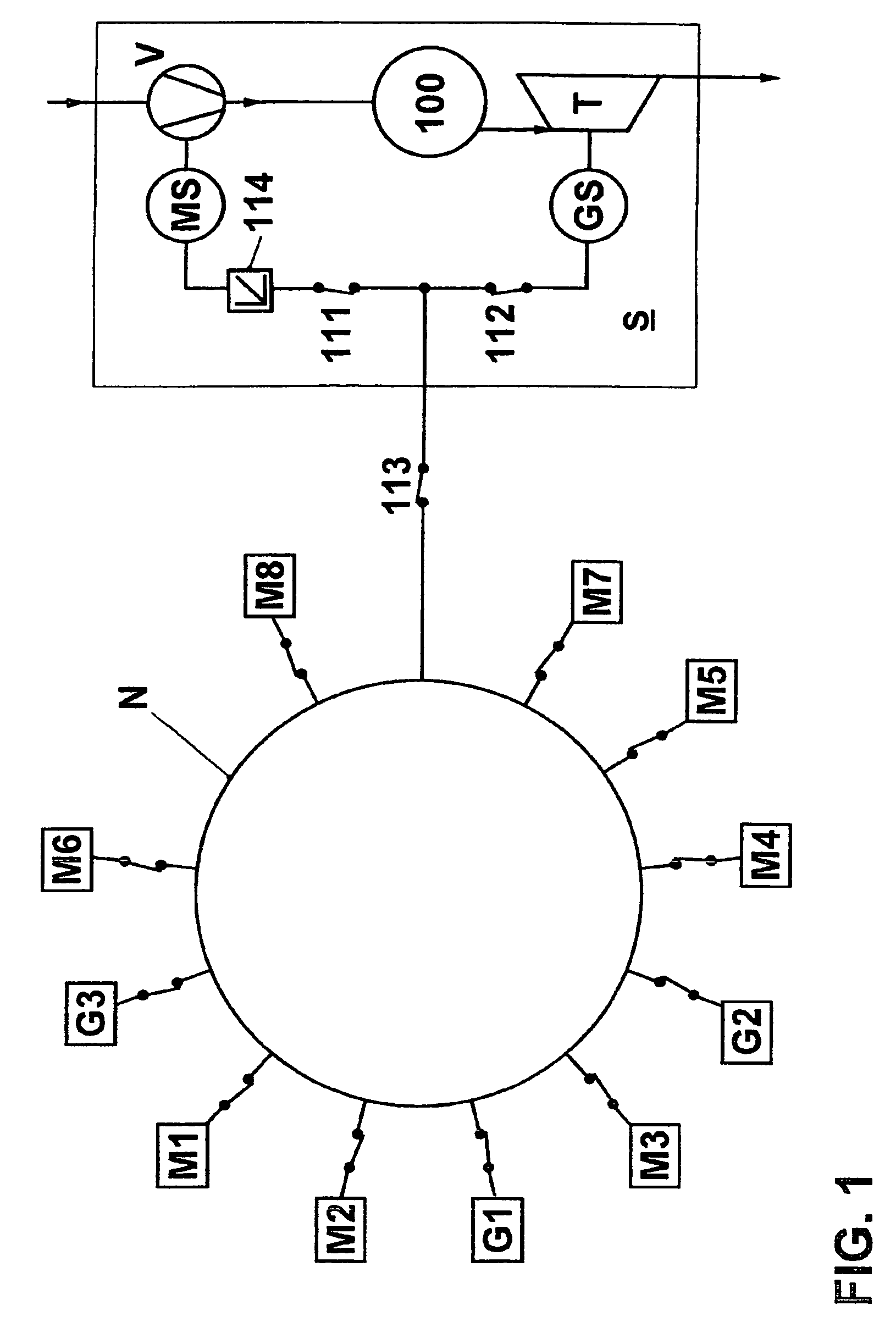
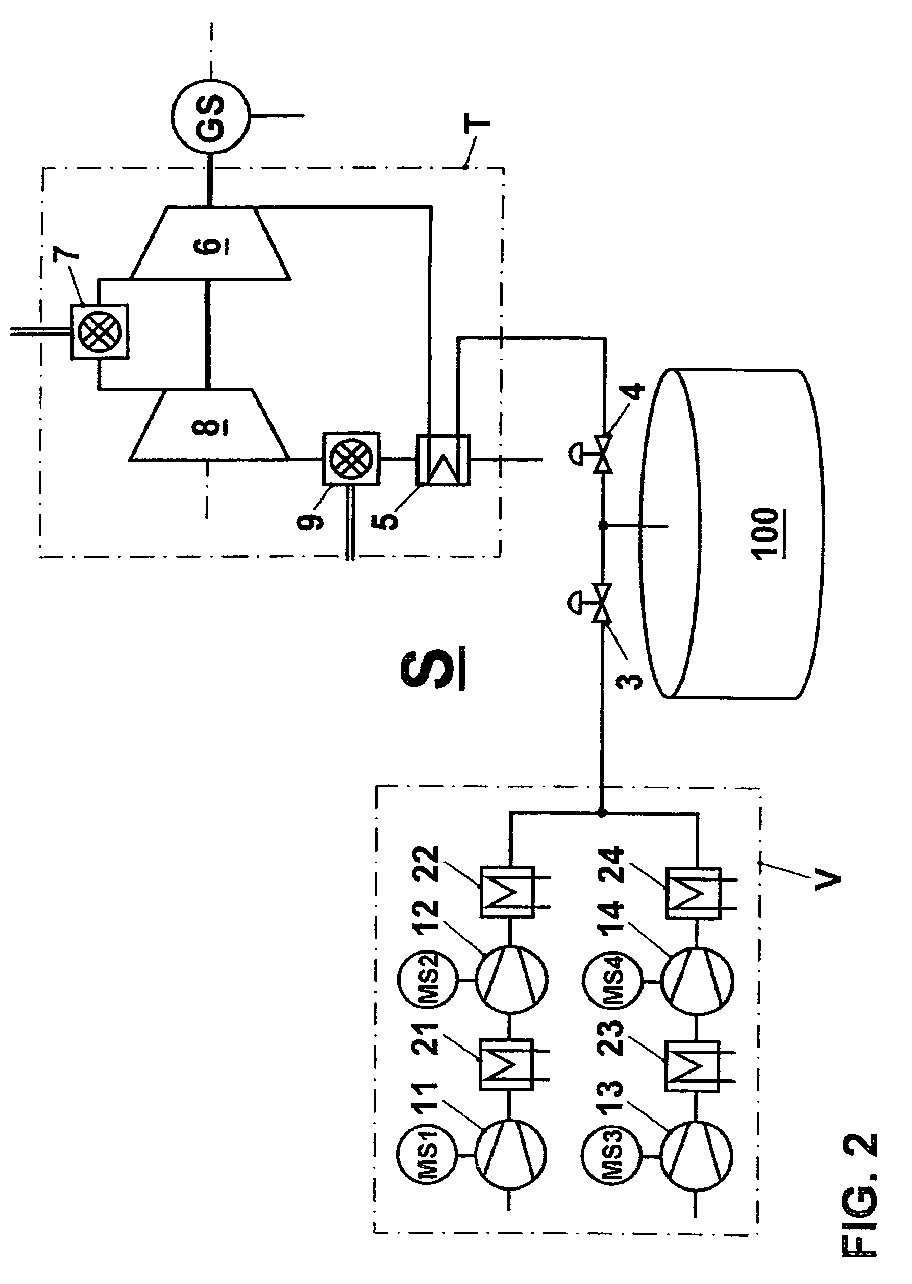
[0013]It is self-evident, for example when a very large block is disconnected from the grid or a large load is connected to it, that it is also necessary to take account of situations in which the additional power demand can no longer be satisfied purely by controlling the power of the power consuming machines; in situations such as these, the power consuming machines are completely disconnected from the grid, and the power generation machine is operated in conjunction with other power stations that are integrated in the grid, in a manner that is known per se, with the maximum power gradient. Assuming that the storage volume has been charged sufficiently, it is possible to react very quickly and flexibly even in this situation. The greatest flexibility and the fastest reaction can in general be achieved when a storage power station comprises two or more compressors which act on a storage volume and can be controlled individually, as well as two or more individually controllable turbines which are fed from this storage volume. One embodiment of a storage power station comprises four compressor systems each having two turbocompressors and intercoolers whose rotation speeds are controlled, as well as two turbine sets, which each act on one generator; the storage power station is operated with storage pressures in the region of 30 bar, and preferably at least 50 bar up to 100 bar.
[0015]When the power demand on the power generation plant is reduced, the power consumption of the power consuming machine is increased, in a first step, while the power output of the power generation machine remains constant, in order to reduce the net power output and at the same time to satisfy the power demand at that time. In a second step, the power output of the power generation machine is then reduced, with the net power output being kept equal to the power demand at that time.
[0017]As described, the method of operation of a storage plant can produce a major effect on the grid by the use of an initial load and by feeding in power, such that it is possibly worth while when, actually for the purpose of transient operations, control of the power demand is handed over from the plant operator to the grid operator.

Problems solved by technology

In this case, the power consuming machine can consume power in particular via an electric drive motor, and the power generation machine can emit power via an electrical generator.
However, the power component to be produced by the power generation machines is available only with a delay since power generation machines which are operated on no load—or to be more precise their generators—must first of all be synchronized to the grid.

Method used


Image

  • Method for operation of a power generation plant
  • Method for operation of a power generation plant
  • Method for operation of a power generation plant

Examples


Embodiment Construction

[0025]Referring to the drawing figures, like reference numerals designate identical or corresponding elements throughout the several figures.

[0026]FIG. 1 shows a schematic view of an electricity grid N. Loads M1 to M8 and three power stations or their generators G1 to G3, as well as an air storage power station S, are connected to the electricity grid via grid switches. An air storage power station such as this has been disclosed, for example, in DE 28 22 575, which disclosure is hereby incorporated by reference and represents an integral component of the present invention. The air storage power station S can include at least one compressor V for filling a storage volume 100 with an energy storage fluid, as well as a turbine T which can be operated with the fluid from the storage volume 100. The turbine T drives a generator GS which generates electrical power which can be fed into the electricity grid via the switch 112. The compressor V is driven by a motor MS which consumes a cont...


PUM

PropertyMeasurementUnit
pressuresaaaaaaaaaa
pressuresaaaaaaaaaa
pressureaaaaaaaaaa

Abstract

A storage power station (S), for example an air storage plant, that includes a compressor unit (V), a turbine unit (T) and a storage volume (100) can be operated using a specific method of operation, which allows as fast a reaction as possible to changes in the load demands. Rapid changes in the load demands can be satisfied by controlling the power consumption of the compressor unit (V), which results in a variable net power output, with the power output from the turbine unit (T) remaining constant. The power of the compressor unit can be controlled approximately one order of magnitude more quickly than the power generation machine can be controlled. In the extreme, the compressor unit can simply be shut down, thus resulting in its drive power becoming available to an electricity grid within seconds. During this process, the turbine unit can continue to operate normally, and can slowly follow the power demand, thus reducing the load on the turbine. A storage power station can thus be ideally suitable for frequency support and for covering rapid load ramps in an electricity grid.

Description

[0001]This application is a Continuation of, and claims priority under 35 U.S.C. § 120 to, International Application number PCT / CH03 / 00431, filed 30 Jun. 2003, and claims priority under 35 U.S.C. § 119 to Swiss Application number 2002 1177 / 02, filed on 04 Jul. 2002, the entireties of which are incorporated by reference herein.BACKGROUND OF THE INVENTION[0002]1. Field of the Invention[0003]The present invention relates to a method for operation of a power generation plant.[0004]2. Description of Related Art[0005]An air storage turbine has been disclosed in DE 28 22 575. At times when the power consumption is low, for example at night and at weekends, a compressor acting as a power consuming machine uses electricity that is generated by basic load power stations to pump air into a storage volume, for example an underground cavern in a salt mine. The cavern is charged, for example, to 100 bar. At times when the electricity demand is high or if another power station fails, the stored ai...

Claims


Application Information

Patent Timeline
Patent Type & Authority Patents(United States)
IPC IPC(8): F01K13/02F01K17/00H02J3/00H02J3/38H02J3/46
CPCF02C6/16H02J3/006H02J3/38H02J3/46Y02E60/15Y04S10/525H02J3/28H02J15/006Y02E60/16H02J3/466
Inventor ALTHAUS, ROLFKOLLER, MARTINWIEDERHOLD, KARL
Owner GENERAL ELECTRIC TECH GMBH
Why Eureka
Try Eureka