Retractable hypodermic needle

a needle system and hypodermic technology, applied in the field of hypodermic needle system, can solve the problem of medical practitioners being inadvertently stuck by needles, and achieve the effect of reducing the risk of needle sticking

Inactive Publication Date: 2008-12-16
VLADIMIRSKY ROMAN
View PDF10 Cites 75 Cited by
  • Summary
  • Abstract
  • Description
  • Claims
  • Application Information

AI Technical Summary

Benefits of technology

[0006]It is another purpose and advantage of this invention to

Problems solved by technology

The larger danger for medical practitioners is the possibility of being inadvertently stuck by a needle which carries on it elements of another person's blood.

Method used


Image

  • Retractable hypodermic needle
  • Retractable hypodermic needle
  • Retractable hypodermic needle

Examples


Embodiment Construction

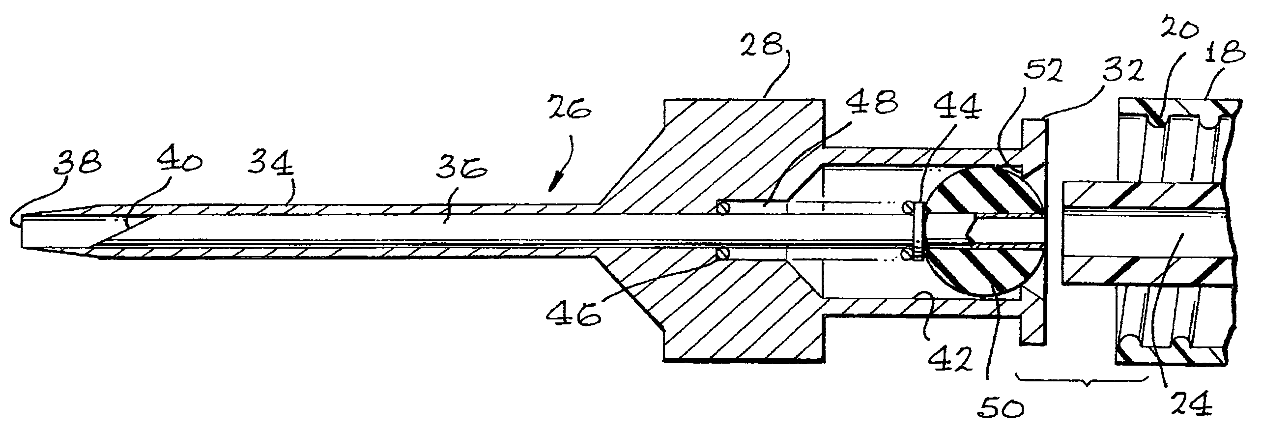
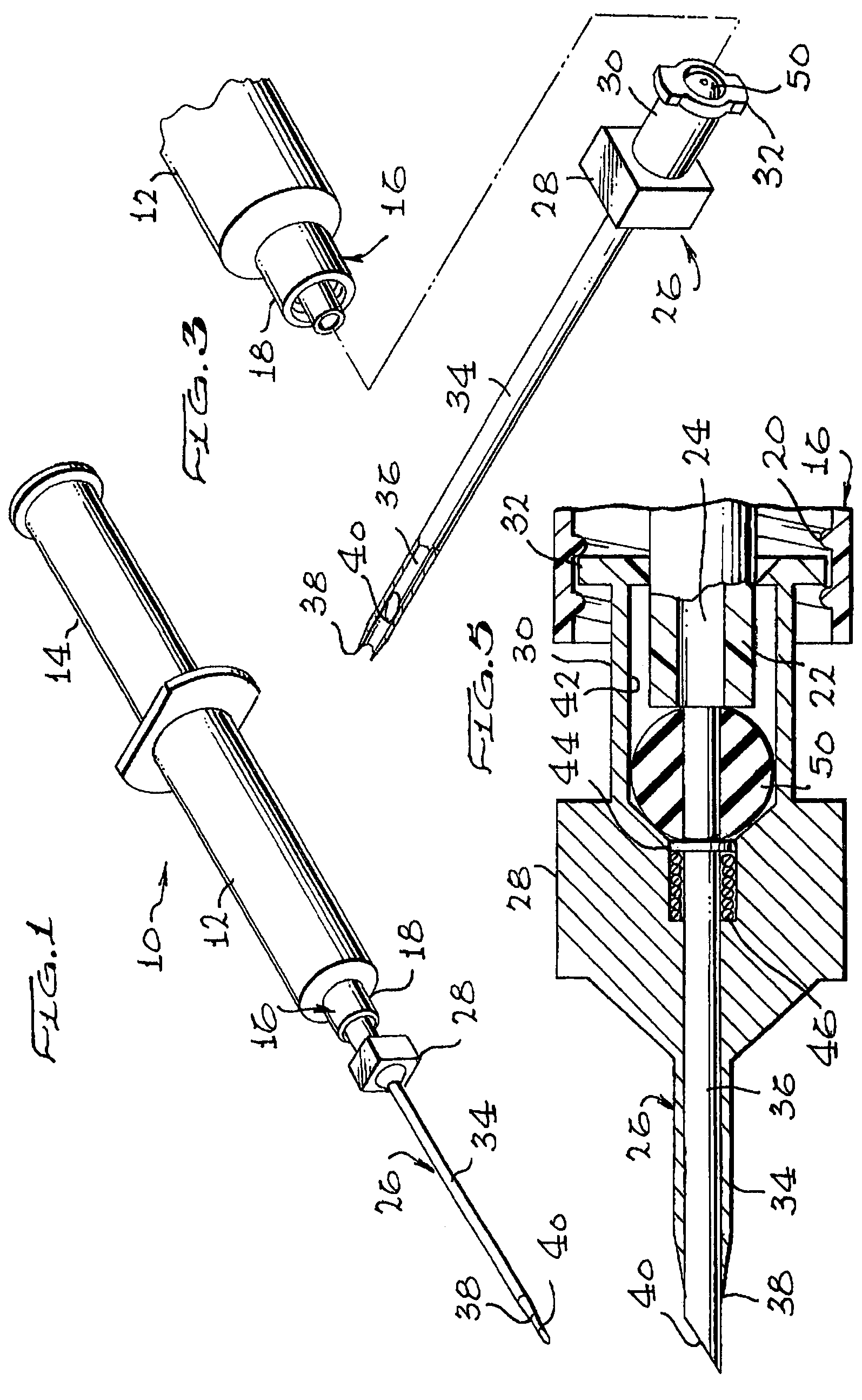
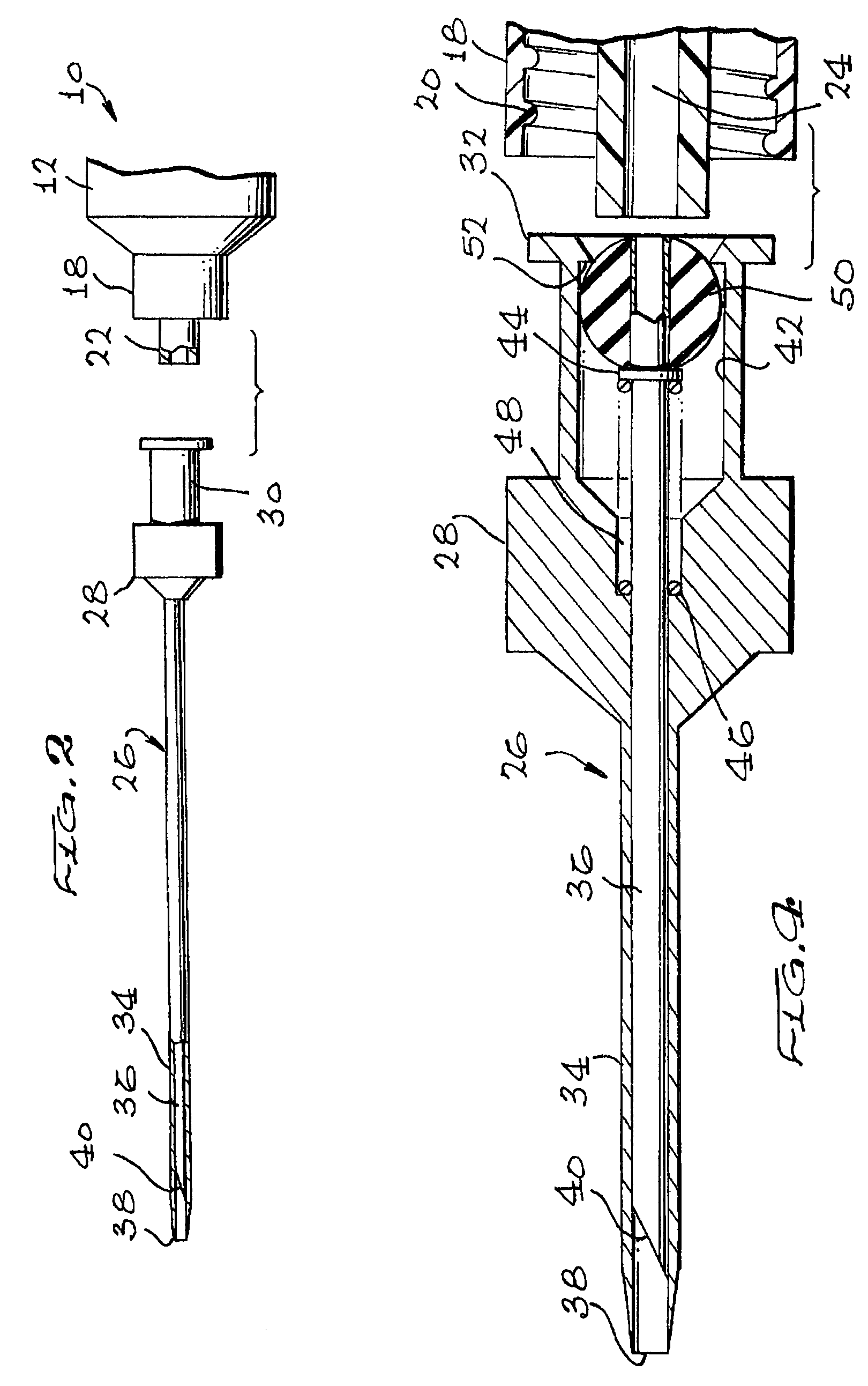
[0018]Syringe 10 is shown in FIG. 1. The syringe 10 is of conventional configuration. It has a barrel 12 in which is slidably-disposed plunger 14. The plunger can slide within the barrel to receive or dispense fluid therefrom. The barrel carries Luer lock 16 thereon. The Luer lock comprises a collar 18 which has interrupted interior threads 20 and nozzle 22 which extends past the collar 18. Nozzle 22 is tapered and has an interior passage 24 which extends into the interior of the barrel. Thus, depression and retraction of plunger 14 moves fluid through passage 24 into or out of the syringe barrel. This is conventional construction.

[0019]The retractable hypodermic needle assembly of this invention is generally indicated at 26 in FIGS. 1, 2, 3, 4, 5, 6, 7 and 8. It comprises a body 28. In the right hand of the body is formed tube 30 which carries fingers 32. The fingers are configured to enter into the collar 18 and engage on the interrupted threads 20 therein. It is these fingers whi...


PUM


Abstract

A needle assembly includes a sheath into which a hypodermic needle is withdrawn in a protected position. Installation of the needle assembly onto a Luer lock causes the needle to be thrust forward out of the sheath. A spring urges the needle to the withdrawn position. An elastomeric ball in the needle assembly provides sealing.

Description

CROSS-REFERENCE[0001]This application relies for priority on my application Ser. No. 60 / 572,445, filed May 19, 2004.FIELD OF THE INVENTION[0002]This invention is directed to hypodermic needle system wherein the needle is retracted into its sheath when the needle assembly is removed from a syringe, to protect personnel against inadvertent needle sticks.BACKGROUND OF THE INVENTION[0003]Hypodermic needles are used in medicine both to inject liquid materials into the body and to withdraw samples from the body. The usual withdrawal is the withdrawal of venous blood. Many infectious diseases are carried in the blood. It has become important in the medical arts to protect the practitioners from contact with possibly-infectious blood. Skin surface contact with blood and other body fluids is not particularly harmful, especially when the skin is healthy. The larger danger for medical practitioners is the possibility of being inadvertently stuck by a needle which carries on it elements of anot...

Claims


Application Information

Patent Timeline
Patent Type & Authority Patents(United States)
IPC IPC(8): A61M5/32
CPCA61B5/1411A61M5/326A61M5/347A61B5/15003A61B5/150236A61B5/150244A61B5/150389A61B5/150473A61B5/150633A61B5/150732A61B5/154
Inventor VLADIMIRSKY, ROMAN
Owner VLADIMIRSKY ROMAN
Why Eureka
Try Eureka