Eureka AIR delivers breakthrough ideas for toughest innovation challenges, trusted by R&D personnel around the world.

SVC-L2.5 VPNs: combining Layer-3 VPNs technology with switched MPLS/IP L2VPNs for ethernet, ATM and frame relay circuits

Inactive Publication Date: 2008-12-16
RPX CLEARINGHOUSE
View PDF13 Cites 18 Cited by
  • Summary
  • Abstract
  • Description
  • Claims
  • Application Information

AI Technical Summary

Benefits of technology

[0013]Advantages of the present invention include real-time establishment of customer Layer-2 virtual circuits (VCs), and the ability to perform dynamic client reconfiguration via dynamic routing. Support for traffic engineering within the L2.5VPN service can be rendered without impacting traffic engineering on the provider network. There is support for an arbitrary mesh topology. In terms of mobility, L2.5VPN allows the ability to move one port of an L2.5VPN from one provider edge device (PE) to another and one provider to another without impacting the L2.5VPN and client network addressing. A further advantage is that L2.5 dynamic bandwidth management supports interworking to legacy Layer-2 VPNs.

Problems solved by technology

Existing varieties of Layer-3 VPNs have limitations affecting ease of implementation and use generating:customers who are not comfortable with Layer-3 VPN IP datapath due to security concerns;customers who want to have flexibility to use Layer-2 circuits for some applications integrated into a Layer-3 VPN;customers who want to improve their Layer-3 management but want control on the datapath;customers who want to use Layer-2 QoS capabilities with IP-VPN service; andcustomers who plan to upgrade to Layer-3 VPN in the future but are not ready to give up their existing Layer-2 networks, for example, Frame Relay networks currently generating revenue.

Method used


Image

  • SVC-L2.5 VPNs: combining Layer-3 VPNs technology with switched MPLS/IP L2VPNs for ethernet, ATM and frame relay circuits
  • SVC-L2.5 VPNs: combining Layer-3 VPNs technology with switched MPLS/IP L2VPNs for ethernet, ATM and frame relay circuits
  • SVC-L2.5 VPNs: combining Layer-3 VPNs technology with switched MPLS/IP L2VPNs for ethernet, ATM and frame relay circuits

Examples


Embodiment Construction

[0027]Glossary of Acronyms Used

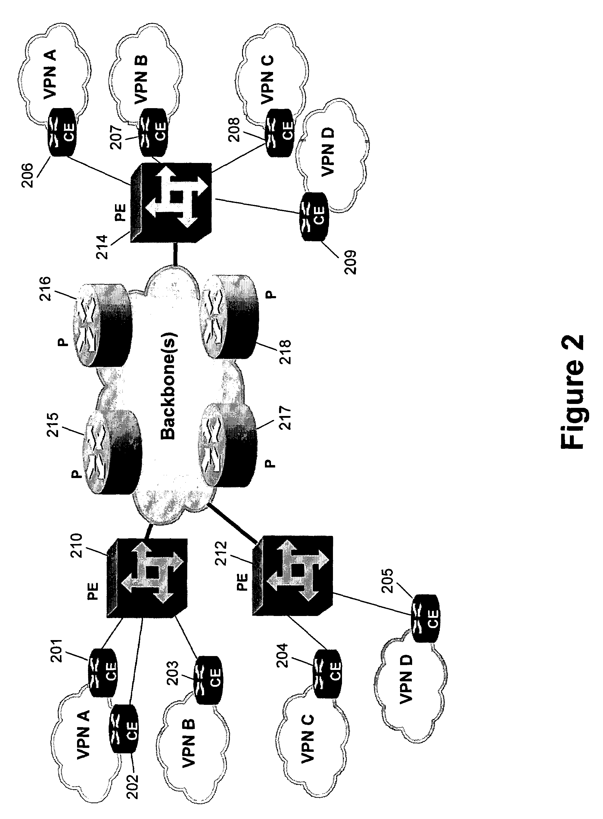
[0028]P—Provider Device

[0029]PE—Provider Edge Device

[0030]CE—Customer Edge Device

[0031]SVC—Switched Virtual Circuit

[0032]CPI—Customer Port Identifier (Layer-2)

[0033]PPI—Provider Port Identifier (Layer-2)

[0034]PIT—Port Information Table

[0035]L2PIT—Layer-2 Port Information Tabl2

[0036]BGP—Border Gateway Protocol

[0037]BGP-AD—BGP Auto-Discovery

[0038]MPLS—Multi-Protocol Label Switching

[0039]DLCI—Data Link Connection Identifier

[0040]LMP—Link Management Protocol

[0041]ISP—Internet Service Provider

[0042]SVC-TE—SVC-L2VPN with Traffic Engineering Capabilities

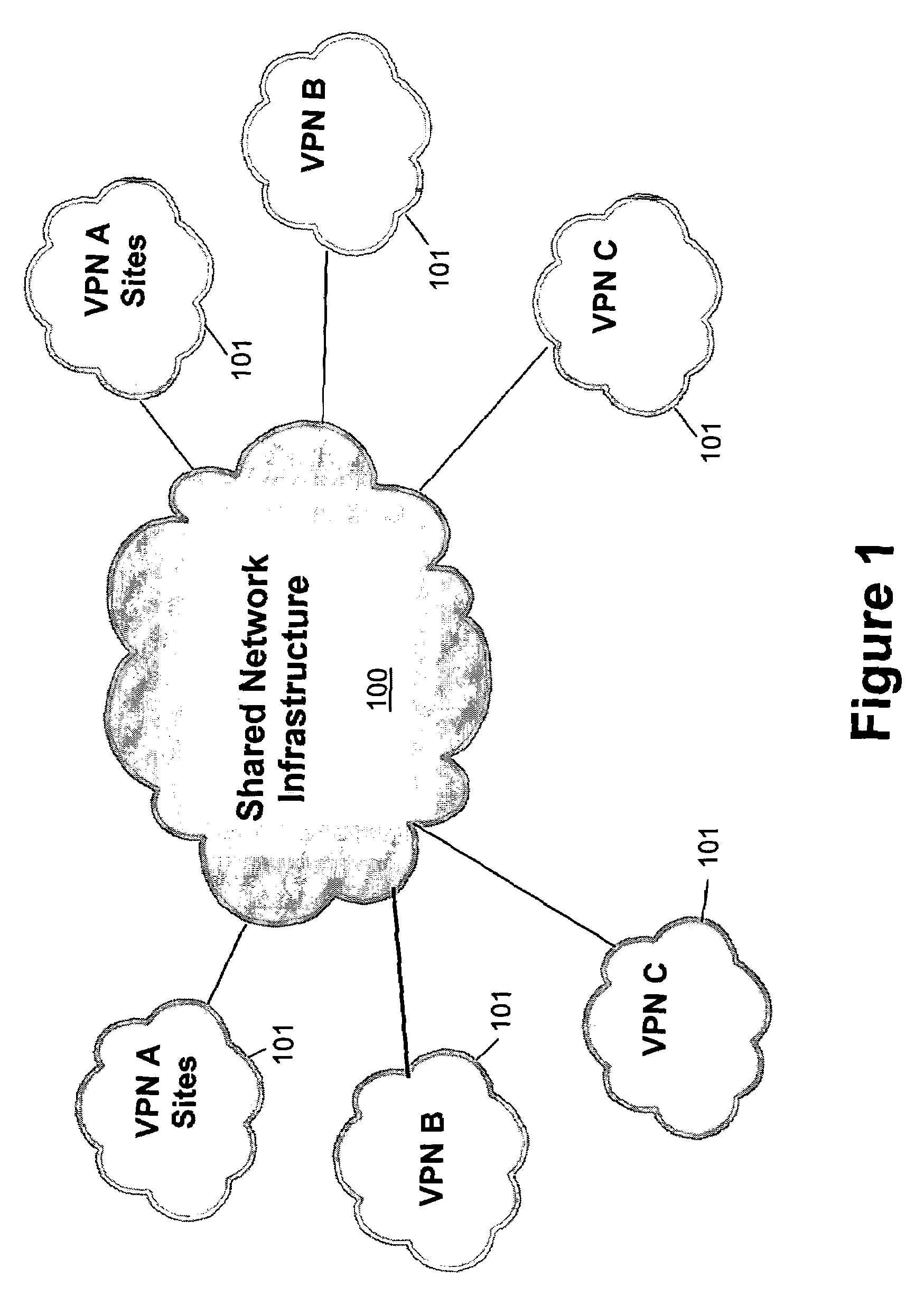
[0043]Referring to FIG. 1, there may be seen a generic network having a shared network infrastructure 100 with connected virtual private network sites 101. The VPN sites 101 make use of the network infrastructure 100 to interconnect physically remote sub-networks of particular VPNs.

[0044]Referring to FIG. 2, there may be seen a network reference model showing a more detailed depiction of a network having a plu...


PUM


Abstract

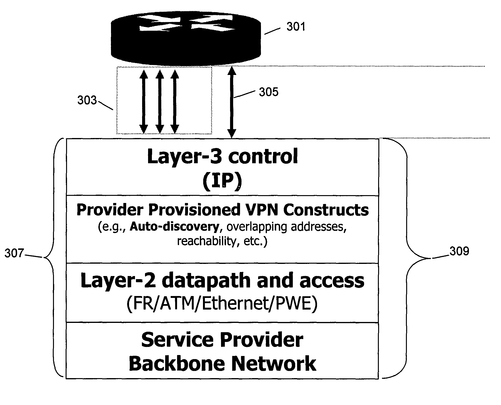
A Layer-2.5 virtual private network arrangement and method is disclosed for switched Layer2VPN combined with a subset of Layer-3 VPNs. The switched virtual circuit Layer-2 VPN includes logical ports of two types, customer and provider, and port information tables, and uses Layer-3 mechanisms to distribute customer routes. This provides simplified provisioning and a degree of customer autonomy regarding establishing of virtual connections without the assistance of the service provider across the service provider's network while allowing the provider to distribute customer reachability information. The switched virtual circuit Layer-2.5 VPN using Layer-3 mechanisms is particularly useful for customers who are not comfortable with a full Layer-3VPN IP datapath due to special security concerns or a desire for Layer-2 QoS with benefits of an IP-VPN service.

Description

RELATED U.S. APPLICATION DATA[0001]Provisional application No. 60 / 409,325 filed on Sep. 9, 2002.FIELD OF THE INVENTION[0002]The present invention relates to a combination of switched Layer-2 Virtual Private Networks (VPNs) with a layer-3 VPN and is particularly concerned with flexible, on-demand switched MPLS / IP Layer-2 VPNs for Ethernet, ATM and Frame Relay SVCs while distributing customer routes through Layer-3 VPN mechanisms.BACKGROUND OF THE INVENTION[0003]A Virtual Private Network (VPN) may be thought of as a private network constructed within a shared network infrastructure. In common terminology, these private networks are used by clients while the network infrastructure is supplied by providers.[0004]Existing varieties of Layer-3 VPNs have limitations affecting ease of implementation and use generating:[0005]customers who are not comfortable with Layer-3 VPN IP datapath due to security concerns;[0006]customers who want to have flexibility to use Layer-2 circuits for some app...

Claims


Application Information

Patent Timeline
Patent Type & Authority Patents(United States)
IPC IPC(8): G06F15/16G06F15/173H04L12/46
CPCH04L12/4675
Inventor OULD-BRAHIM, HAMID
Owner RPX CLEARINGHOUSE
Why Eureka
Eureka Blog
Learn More