Air-conditioning system and a method for the preparation of air for the air-conditioning of a space

Active Publication Date: 2008-12-23
LIEBHERR AEROSPACE LINDENBERG
View PDF22 Cites 36 Cited by
  • Summary
  • Abstract
  • Description
  • Claims
  • Application Information

AI Technical Summary

Benefits of technology

[0008]It is therefore the object of the present invention to further develop an air-condit

Problems solved by technology

The tapping of the fresh air to be treated directly from the engine is, however, problematic to the extent th

Method used


Image

  • Air-conditioning system and a method for the preparation of air for the air-conditioning of a space
  • Air-conditioning system and a method for the preparation of air for the air-conditioning of a space
  • Air-conditioning system and a method for the preparation of air for the air-conditioning of a space

Examples


Embodiment Construction

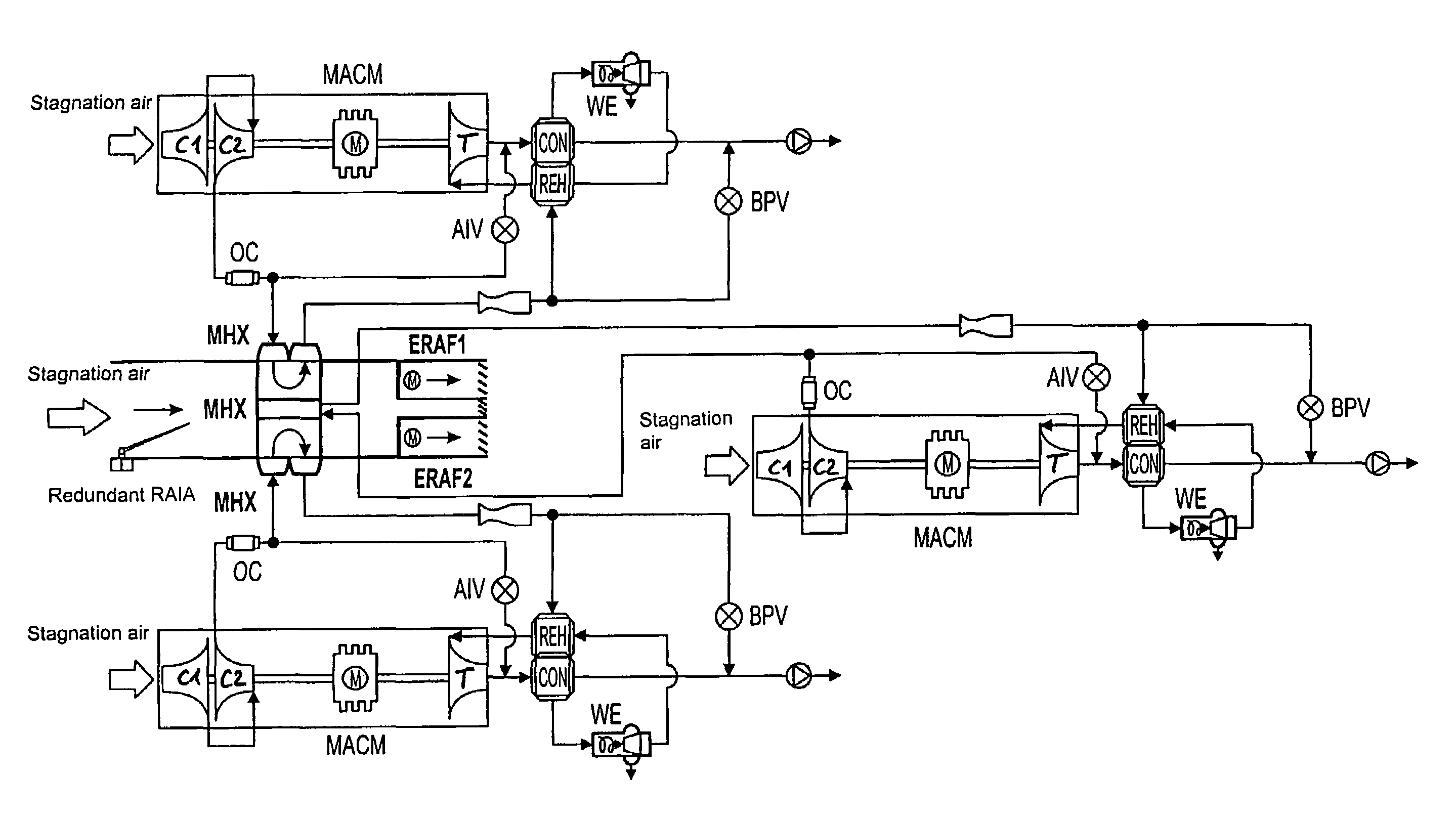
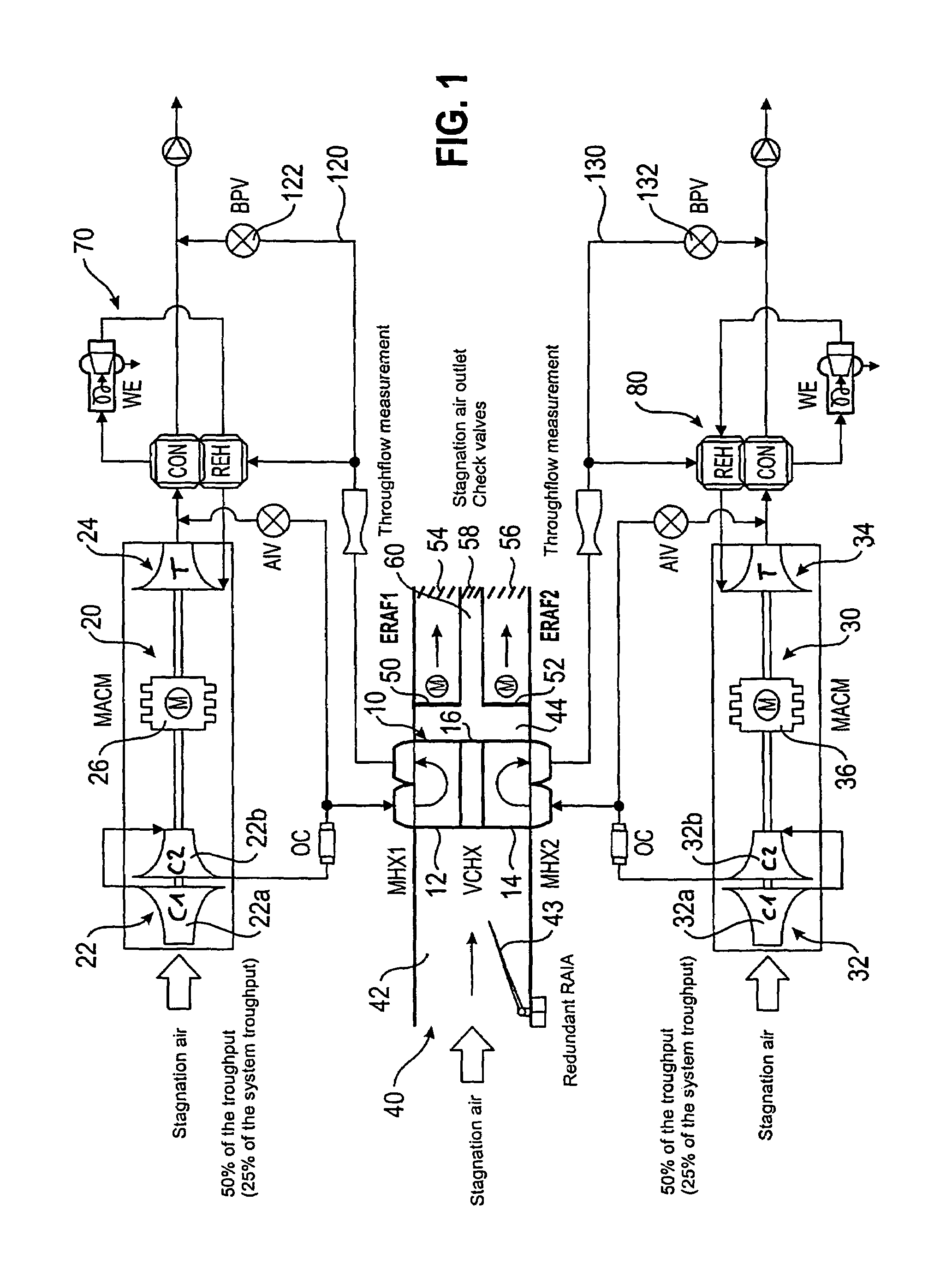
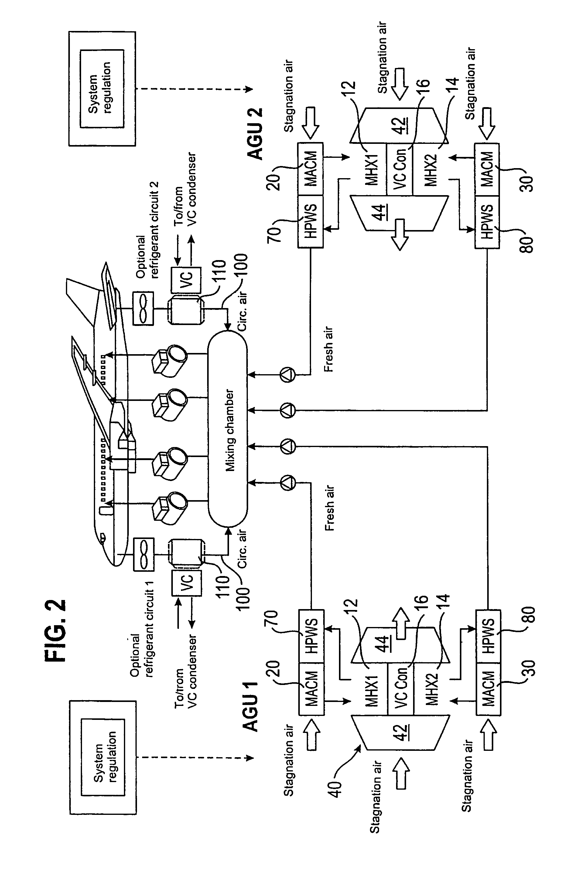
[0045]FIG. 1 shows a schematic representation of an air-conditioning system having two motor-powered shaft devices 20, 30 which each consist of a two-stage compressor 22, 32 of a turbine 24, 34 and of an electric motor 26, 36 for the supplementary driving of the compressors 22, 32. The shaft devices are provided with the designation MACM in the figures.

[0046]The air-conditioning system furthermore has a common stagnation air passage 40 in which the heat exchanger units 12, 14 separate from one another on the compressed air side are arranged which are furthermore given the designations MHX1 and MHX2 in the Figures. A further heat exchanger unit 16 is located between the heat exchanger units 12, 14 separate on the compressed air side and is not in communication with any of the heat exchanger units 12 or 14 on the compressed air side and is furthermore given the designations VCHX and VCCon in the Figures. The further heat exchanger unit 16 can be located between the two heat exchanger ...


PUM


Abstract

The present invention relates to an air-conditioning system, in particular an air-conditioning system for the air-conditioning of a passenger cabin of an airplane, having at least one heat exchanger arranged in a stagnation air passage for the cooling of compressed air and having at least one first shaft device and one second shaft device, with the heat exchanger including at least one first heat exchanger unit and one second heat exchanger unit separate from it on the compressed air side, which are arranged in the common stagnation air passage and of which a respective one is in communication on the compressed air side with a respective one of the shaft devices, with the shaft devices having compressors which are in respective communication on the outlet side with the inlet of the heat exchanger units on the compressed air side. The compressors are acted on by stagnation air or environmental air on the inlet side and are driven by means of one or more motors. The invention further relates to a method for the preparation of air for the air-conditioning of a space.

Description

BACKGROUND OF THE INVENTION[0001]The invention relates to an air-conditioning system, in particular an air-conditioning system for the air-conditioning of a passenger cabin of an airplane in accordance with the description herein. The invention further relates to a method for the preparation of air for the air-conditioning of a space, in particular for the air-conditioning of a passenger cabin of an airplane.[0002]Air-conditioning systems for airplanes are known in numerous different embodiments. They in particular serve the heating and the cooling of the cabin, the cabin pressurization and the supply of fresh air. What is important is that the air-conditioning system has a construction size and a weight which are as low as possible, which is in particular of great interest in aircraft construction. Already known air-conditioning systems as a rule have a shaft device which includes a compressor and a turbine and which can additionally be provided with a blower arranged in a stagnati...

Claims


Application Information

Patent Timeline
IPC IPC(8): F25D9/00B64D13/06F25B9/00
CPCB64D13/06F25B9/004B64D2013/0618B64D2013/064B64D2013/0644B64D2013/0648B64D2013/0688Y02T50/56Y02T50/50
Inventor BRUTSCHER, NORBERTHAAS, JOACHIM
Owner LIEBHERR AEROSPACE LINDENBERG
Why Eureka
Try Eureka