Coil forming and inserting device and coil forming and inserting method

a coil and coil technology, applied in the field of coil forming and insertion devices, can solve the problems of unreliable transfer and mounting of the monopole coil, the monopole coil cannot drop, etc., and achieve the effect of convenient supply, convenient wounding, and convenient supply

Inactive Publication Date: 2008-12-23
AISIN AW CO LTD
View PDF6 Cites 10 Cited by
  • Summary
  • Abstract
  • Description
  • Claims
  • Application Information

AI Technical Summary

Benefits of technology

[0008]The present invention is made in consideration of the problems associated with the above-described conventional apparatus, and provides a coil forming and insertion device and a coil forming and insertion method providing a constant length for the connecting wires connecting the respective monopole coils. Further, the apparatus of the present invention is capable of mounting the multipole coils approximately simultaneously and reliably delivering each monopole coil to coil receiving portions almost without change from the state in which multipole coil is formed.

Problems solved by technology

However, there exists the possibility that, in certain cases, the monopole coil can not drop to the clearance.
Accordingly, transfer and mounting of the monopole coil is unreliable.

Method used


Image

  • Coil forming and inserting device and coil forming and inserting method
  • Coil forming and inserting device and coil forming and inserting method
  • Coil forming and inserting device and coil forming and inserting method

Examples


first embodiment

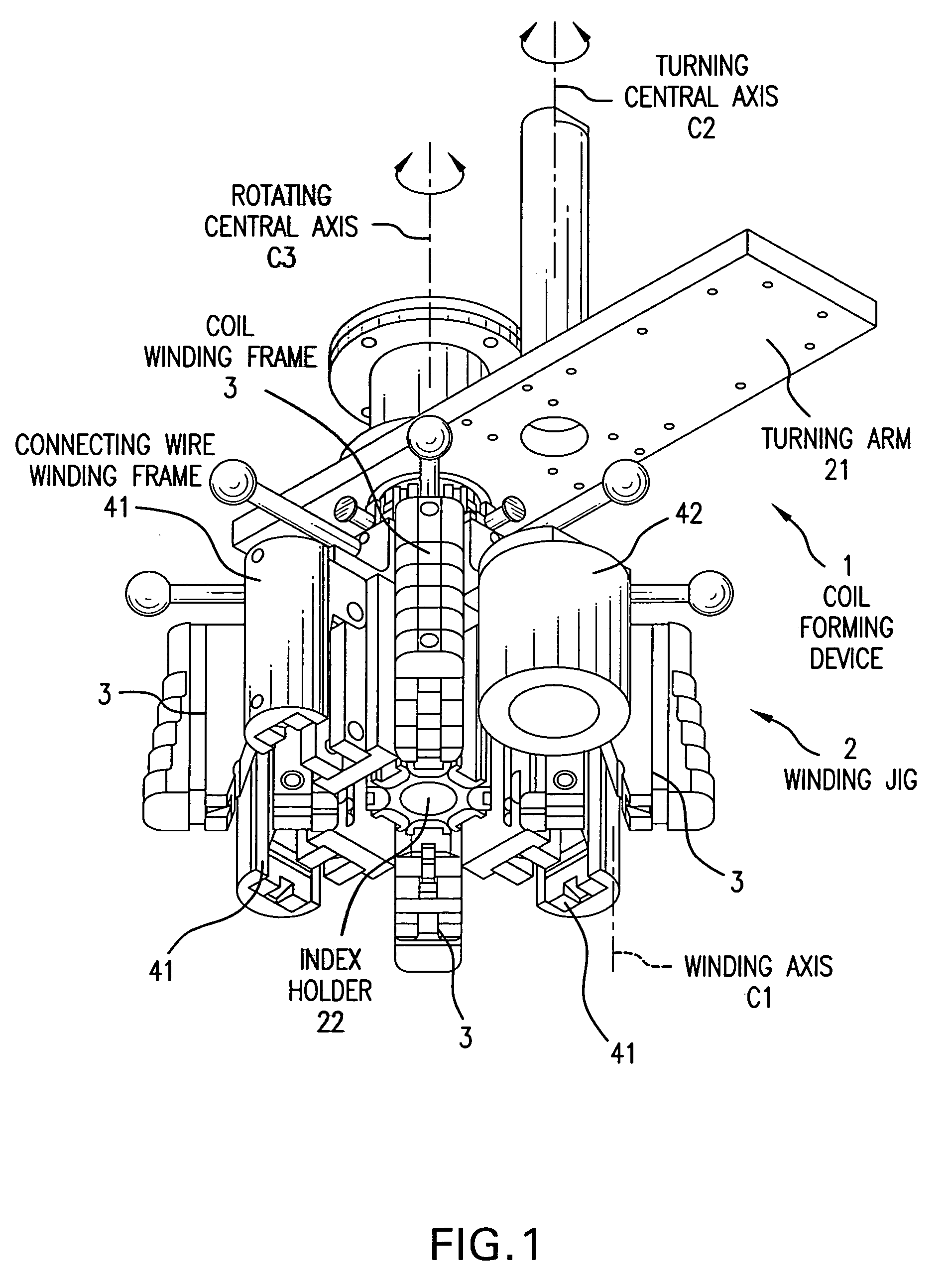
[0068]A first embodiment of coil forming apparatus and method, with formation of a multipole coil, will now be described with reference to FIGS. 1 to 11.

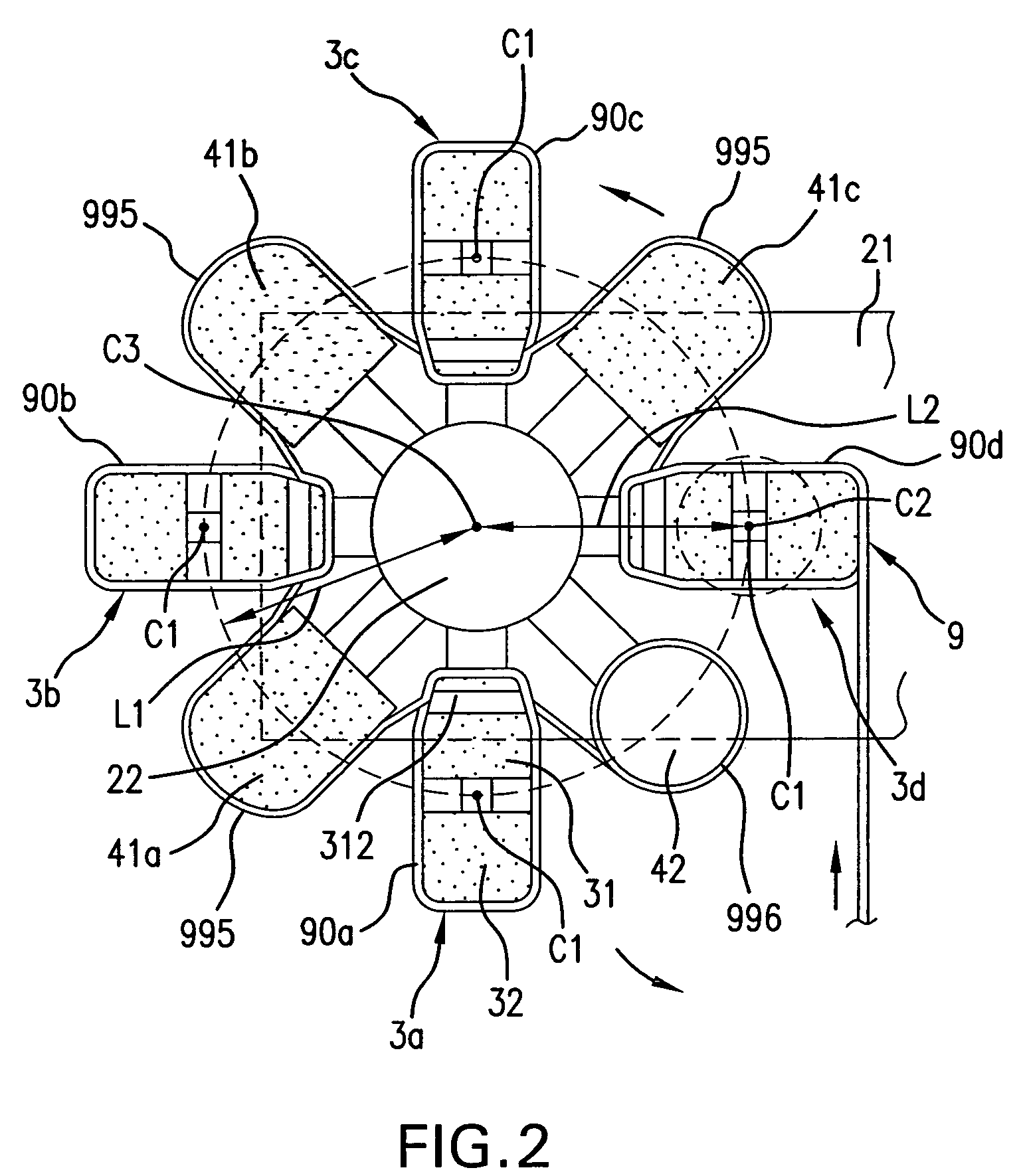
[0069]As shown in FIGS. 1 and 2, the coil forming device 1 of the first embodiment forms a multipole coil 9 joining plural monopole coils 90. The coil forming device 1 is shown as including an unillustrated base frame, a turning arm 21 supported in the base frame for rotation around a central axis C2, and a winding jig 2. The winding jig 2 has an index holder 22 mounted for movement relative to the turning arm 21, and plural coil winding frames 3 arranged around the outer circumference of index holder 22.

[0070]The winding axes C1 for winding the electric wire 99 around the coil winding frames 3 are approximately parallel and also approximately parallel to the central turning axis C2. The coil forming device 1 is constructed such that the coil winding frames 3 for winding the above electric wire 99 can sequentially approach the centr...

second embodiment

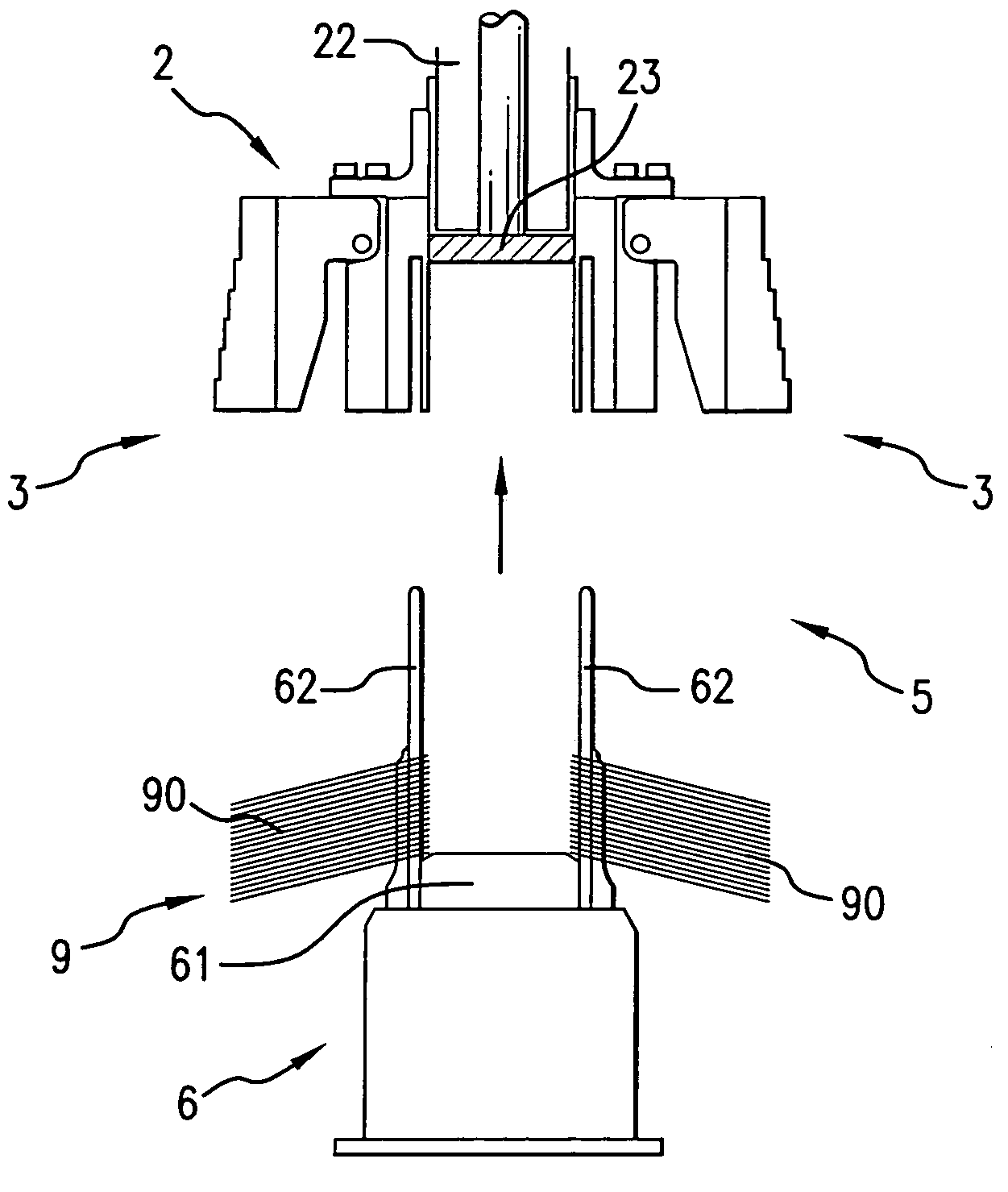
[0106]A coil forming insertion device and a coil forming insertion method in accordance with the second embodiment, utilizing a winding jig and a inserter jig will now be explained with reference to FIGS. 12 to 20. Further, a method for transferring the multipole coil held on the winding jig to the inserter jig, and a method for transferring the multipole coil from the inserter jig into slots of the stator core will also be explained.

[0107]Further, the winding jig used in the second embodiment is the same as the winding jig used in the first embodiment, and may also be explained by reference to FIGS. 1 to 11.

[0108]As shown in FIG. 13, the coil forming and insertion device 5 of this second embodiment includes a winding jig 2 and an inserter jig 6. The winding jig 2 forms the multipole coil 9 by joining plural monopole coils 90 formed by winding the electric wire 99 in a loop shape. The inserter jig 6 is axially aligned in opposition to this winding jig 2 and receives the multipole co...


PUM

PropertyMeasurementUnit
multipoleaaaaaaaaaa
distanceaaaaaaaaaa
diameteraaaaaaaaaa

Abstract

A coil forming and insertion apparatus includes plural coil winding frames, a winding jig for forming a multipole coil, plural coil receiving portions, and an inserter jig for inserting and arranging the multipole coil in slots of a stator core. The coil forming and insertion apparatus has each coil receiving portion opposed to a coil winding frame, the multipole coil is formed by connecting the monopole coils wound on the coil winding frames and the multipole coil is transferred from the winding jig to the inserter jig.

Description

CROSS-REFERENCE TO RELATED APPLICATIONS[0001]This application is a National Phase Application (35 USC 371) of PCT / JP2004 / 005650 and claims priority of Japanese Application No. 2003-116222, filed Apr. 21, 2003.TECHNICAL FIELD[0002]The present invention relates to a coil forming and insertion device and to a method for forming a coil and for inserting and arranging this coil in a stator core to be incorporated into an electric motor.BACKGROUND ART[0003]In the manufacture of a motor having a stator with slots for insertion of plural monopole coils into slots of the stator core, a multipole coil is formed by joining the plurality of the monopole coils.[0004]In a conventional coil forming method, a winder guiding an electric wire (wire) travels around a fixed winding frame, and the electric wire is wound around the winding frame to form the monopole coil.[0005]JP-A-2000-253631 discloses a winding apparatus including a winding frame with a changeable outside diameter and a flyer which is ...

Claims


Application Information

Patent Timeline
Patent Type & Authority Patents(United States)
IPC IPC(8): B21F3/00B21F3/04B21F45/00H02K15/085H02K15/04
CPCH02K15/0435Y10T29/49073Y10T29/49071Y10T29/53213
Inventor HASHIMOTO, SHINGOKUROYANAGI, TOORU
Owner AISIN AW CO LTD
Why Eureka
Try Eureka