Supercharge Your Innovation With Domain-Expert AI Agents!

Backlight unit and method of manufacturing a polarization film employed in the same

a polarization film and backlight unit technology, applied in the direction of polarizing elements, instruments, optics, etc., can solve the problems of difficult metal pattern formation, poor transmission efficiency of multi-layered reflective polarization film, difficult to achieve accurate metal patterns, etc., to reduce the manufacturing period of polarization film

Inactive Publication Date: 2008-12-23
LG ELECTRONICS INC
View PDF10 Cites 1 Cited by
  • Summary
  • Abstract
  • Description
  • Claims
  • Application Information

AI Technical Summary

Benefits of technology

The present invention provides a backlight unit with a polarization film that uses UV curing resin and metal substance to function as a reflective polarization film. The method of manufacturing the polarization film involves applying UV curing resin on a transparent film, disposing a patterned film, irradiating with ultraviolet rays, and then adding metal substance to form lines on the film. This method reduces the manufacturing period of the polarization film and allows for its production in large quantities. The use of UV curing resin and metal substance also results in a more durable and reliable polarization film.

Problems solved by technology

However, the thin multi-layered reflective polarization film is not good in the transmission efficiency for a particular wavelength and also is not good in the reflection efficiency for other wavelength.
However, it is difficult to form accurately the metal patterns 152 on the transparent substrate 150, and so a process of manufacturing one reflective polarization film 148 has to be long.
Accordingly, it is difficult to manufacture in great quantities the reflective polarization film 148.

Method used


Image

  • Backlight unit and method of manufacturing a polarization film employed in the same
  • Backlight unit and method of manufacturing a polarization film employed in the same
  • Backlight unit and method of manufacturing a polarization film employed in the same

Examples


Embodiment Construction

[0037]Hereinafter, the preferred embodiments of the present invention will be explained in more detail with reference to the accompanying drawings.

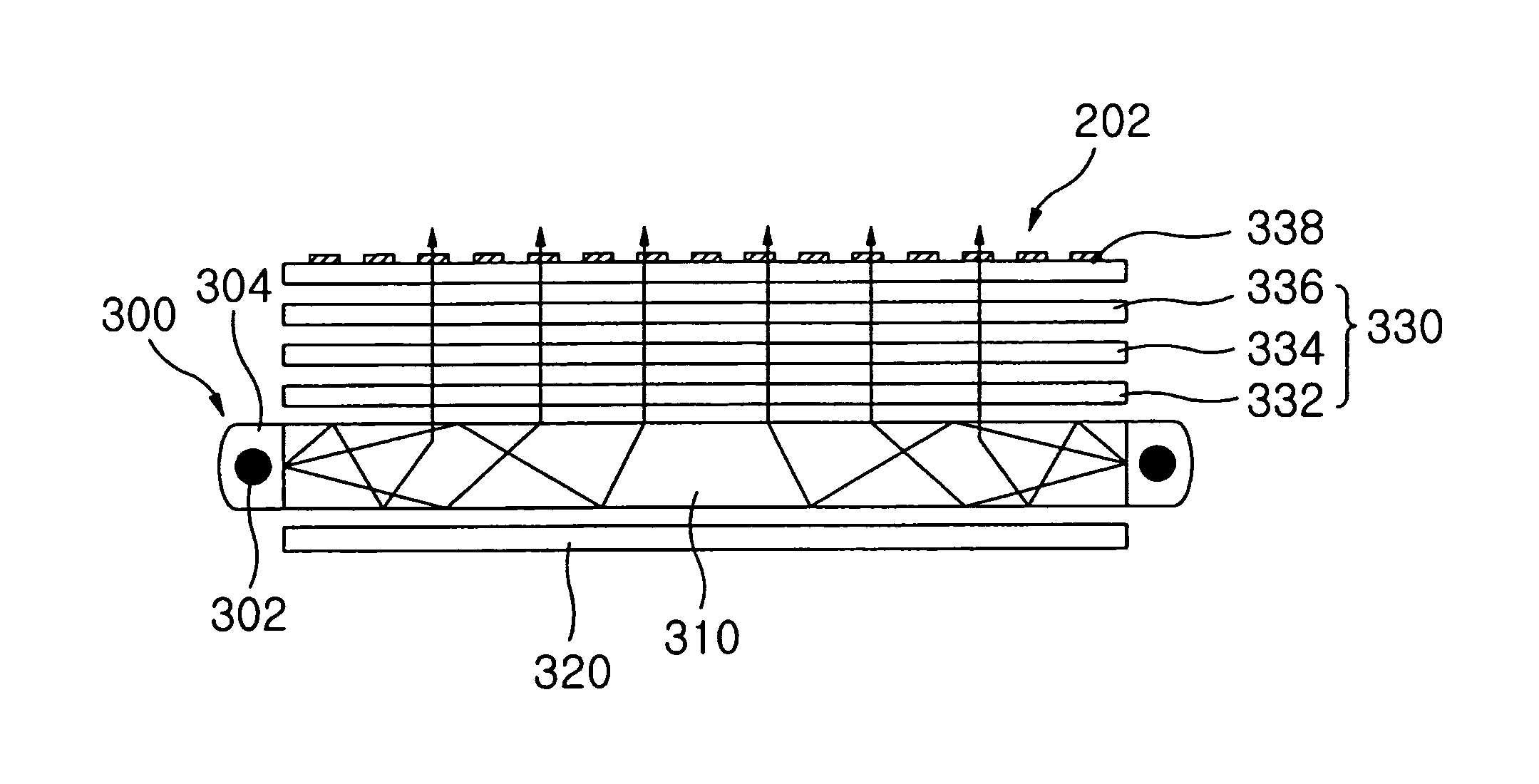
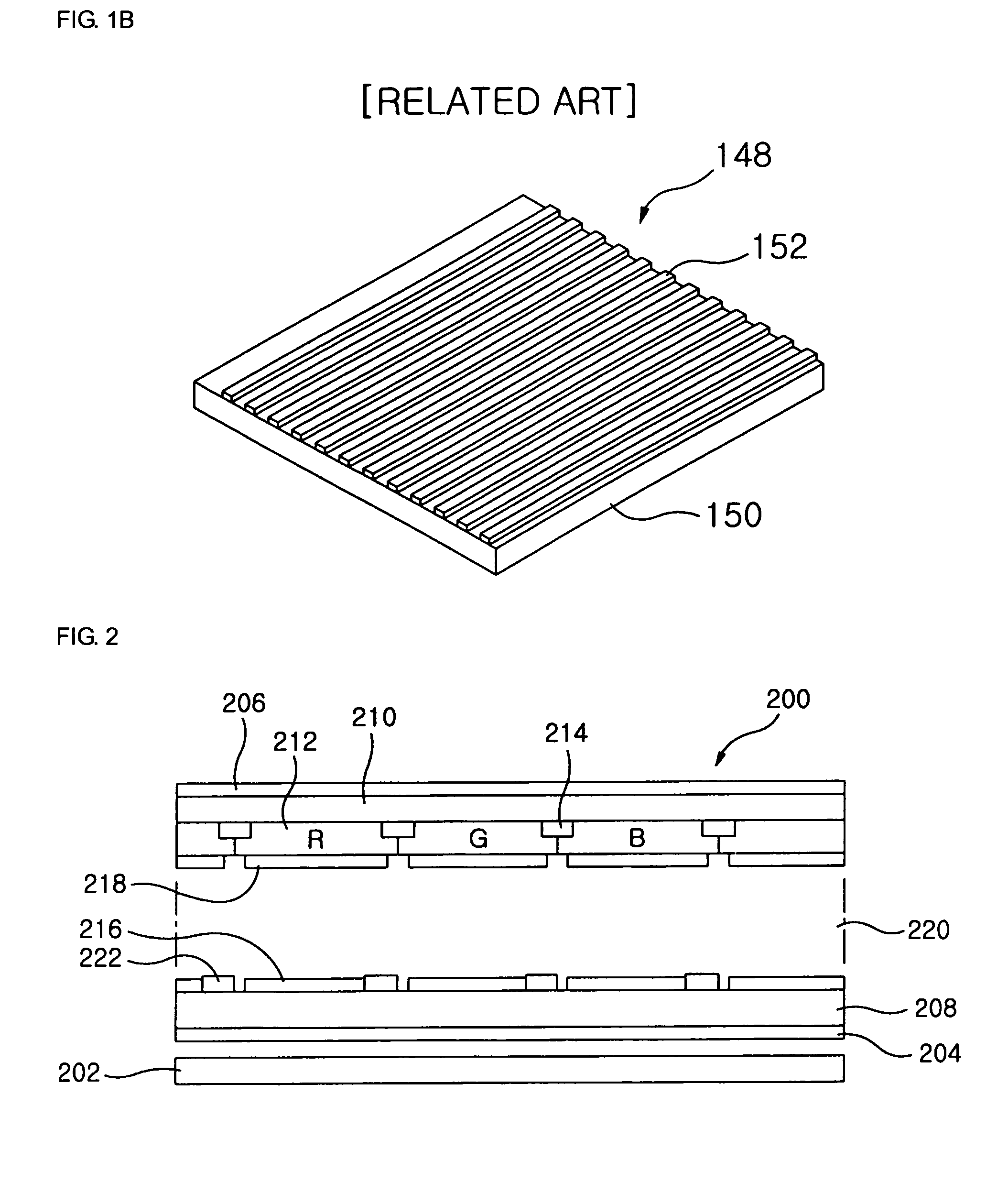
[0038]FIG. 2 is a sectional view illustrating a liquid crystal display employing a backlight unit according to one embodiment of the present invention. FIG. 3A to FIG. 3C are sectional views illustrating the backlight unit according to one embodiment of the present invention.

[0039]In FIG. 2, the liquid crystal display (hereinafter, referred to as “LCD”) includes a LCD panel 200 and a backlight unit (hereinafter, referred to as “BLU”) 202.

[0040]The LCD panel 200 includes a lower polarization film 204, an upper polarization film 206, a lower glass substrate 208, an upper glass substrate 210, a color filter 212, a black matrix 214, a pixel electrode 216, a common electrode 218, a liquid crystal layer 220 and a TFT array 222.

[0041]The color filter 212 includes sub-color filters corresponding to red, green and blue light.

[0042]The TFT array 22...


PUM


Abstract

A backlight unit having a polarization film for performing the function of a reflective polarization film, wherein the backlight unit includes a light source, an optical film and a polarization film. The light source emits a light having a certain wavelength, the optical film is located proximate to the light source to transmit the light outputted from the light guiding plate in a certain direction, and the polarization film is located proximate to the optical film. Here, the polarization film has a UV curing resin and lines disposed on the UV curing resin, and polarizes the light transmitted from the optical film. The backlight unit manufactures the polarization film by using an UV curing resin and a metal substance, and thus the manufacture period of the polarization film may be reduced enabling the polarization film to be manufactured in great quantities.

Description

BACKGROUND OF THE INVENTION[0001]1. Field of the Invention[0002]The present invention relates to a backlight unit and a method of manufacturing a polarization film employed in the same. More particularly, the present invention relates to a backlight unit having a polarization film for performing the function of a reflective polarization film and a method of manufacturing the polarization film employed in the same.[0003]2. Description of the Related Art[0004]A Liquid crystal display (hereinafter, referred to as “LCD”) displays an image using change of the transmissivity of liquid crystals in LCD. The LCD is not a self light-emitting device, and so includes a backlight unit (hereinafter, referred to as “BLU”) for providing a light to a panel located over the BLU.[0005]FIG. 1A is a sectional view illustrating the BLU employed in the LCD.[0006]In FIG. 1A, the BLU 100 is driven by edge-light method, and includes a light source unit 110, a light guiding plate 120, a reflector 130, an opti...

Claims


Application Information

Patent Timeline
Patent Type & Authority Patents(United States)
IPC IPC(8): G02B27/28
CPCG02B5/3025G02F1/133528G02F2001/133548Y10S359/90G02F1/133548G02B5/30G02F1/1335
Inventor LEE, JUNG HOONLEE, SANG GONKIM, KANG YOONKIM, CHANG JONGHWANG, KAB JIN
Owner LG ELECTRONICS INC
Features
  • R&D
  • Intellectual Property
  • Life Sciences
  • Materials
  • Tech Scout
  • Unparalleled Data Quality
  • Higher Quality Content
  • 60% Fewer Hallucinations
Learn More